Ear-wing

a technology of ear wings and earpieces, applied in the direction of transducer details, earpiece/earphone attachment, electrical transducer, etc., can solve the problems of user discomfort, wear comfort, and difficulty in adjusting the earphones to the ears of users, and achieve the effect of minimizing the pressure applied

Active Publication Date: 2017-09-26
CRESYN
View PDF8 Cites 6 Cited by
  • Summary
  • Abstract
  • Description
  • Claims
  • Application Information

AI Technical Summary

Benefits of technology

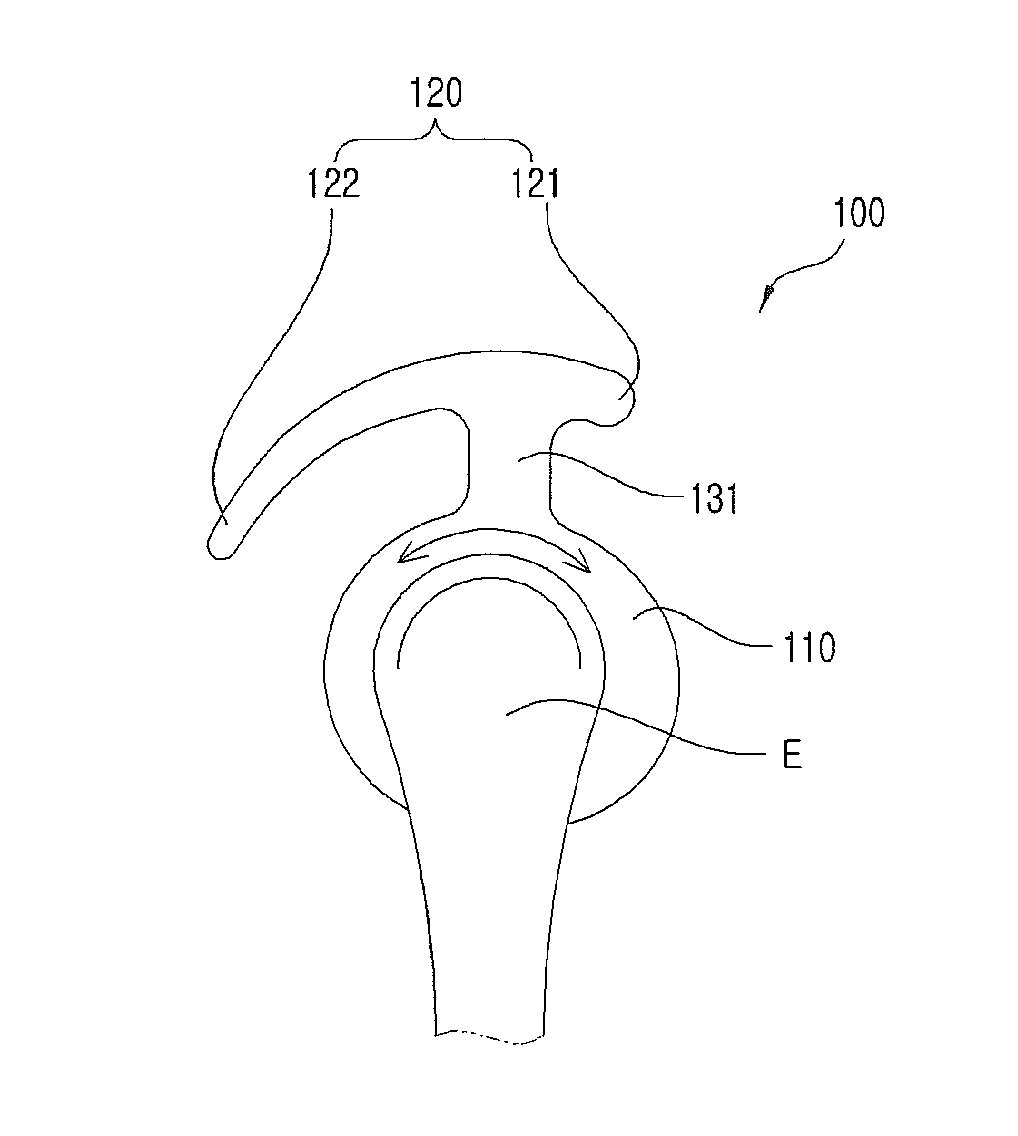
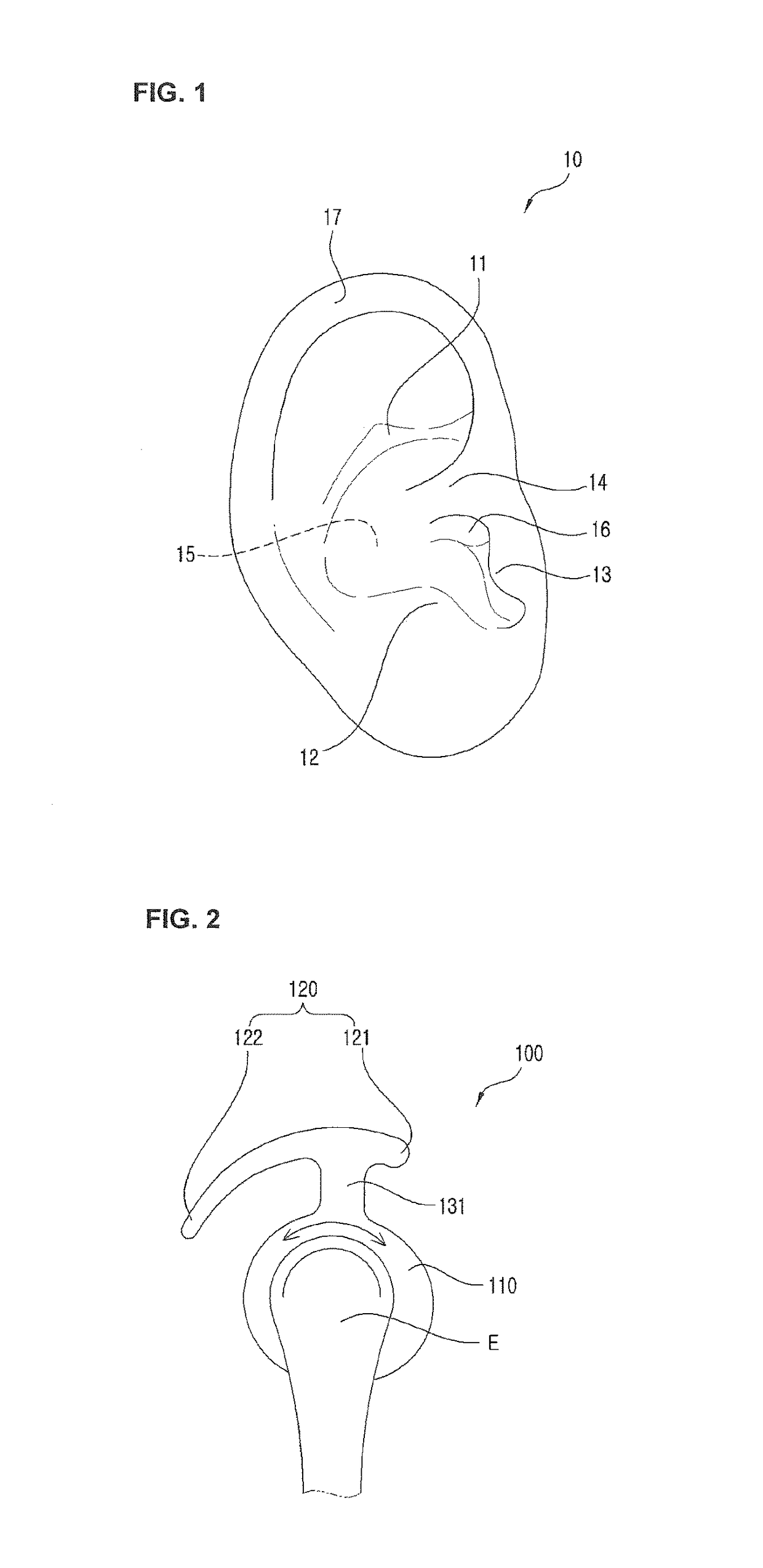
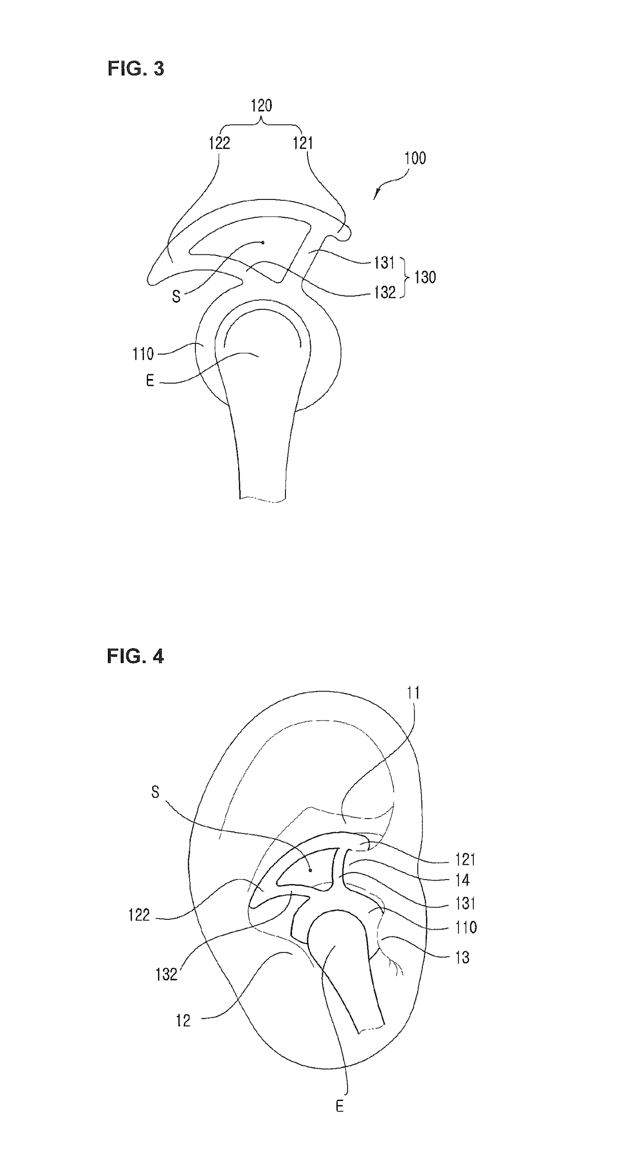
[0010]Accordingly, the present invention has been made in view of the above-mentioned problems occurring in the prior art, and it is an object of the present invention to provide an ear wing that is capable of allowing the position of a sound output device to be contactedly fixed stably to an external ear and further minimizing the pressure applied to the antitragus and the tragus.

Problems solved by technology

However, eartips of recently launched earphones, which are worn on the ears of users, have almost uniform shapes, and when considering different ear structures and features according to users, accordingly, it is difficult that the earphones are fixed to the ears of the users.
If the earpiece is worn for long hours, accordingly, the portions around the antigragus and the tragus may be compressed against the outer leg and the inner leg, thus causing wearing comfort to be bad and making the user feel uncomfortable.

Method used


Image

  • Ear-wing
  • Ear-wing
  • Ear-wing

Examples


Embodiment Construction

[0025]Hereinafter, if it is determined that the detailed explanation on the well known technology related to the present invention makes the scope of the present invention not clear, the explanation will be avoided for the brevity of the description. Further, terms, such as the first and the second may be used to describe various elements, but the elements should not be restricted by the terms. The terms are used to only distinguish one element from the other element.

[0026]Further, the terms used in the specification and claims are not limitedly interpreted only as the meanings defined in dictionaries, and they should be interpreted as having the meanings and concepts corresponding to the technical ideas of the present invention, on the basis of the principle where the concepts of the terms can be appropriately defined by the inventor so that the invention is explained in the best way.

[0027]Accordingly, the configurations in the embodiments and drawings of the specification are just...


PUM


Abstract

The present invention relates to an ear wing including: a coupling portion coupled to a sound output device; a deformable fixing portion deformed with a curvature to correspond to the shape of the antihelix in such a manner as to be located inside the antihelix and for fixing the position of the coupling portion to an external ear; and a variable portion for connecting the coupling portion and the deformable fixing portion in such a manner as to support the deformable fixing portion thereagainst and having at least one or more variable parts changed in shape according to the deformation of the deformable fixing portion. In addition, according to the present invention, the pressure applied to the surrounding portions of the antitragus and the tragus can be minimized through the structure of connecting the coupling portion and the variable portion, so that wearing comfort becomes excellent, and even if the user wears the ear wing for long hours, he or she does not feel uncomfortable, thus optimizing the conveniences in use.

Description

BACKGROUND OF THE INVENTION[0001]Field of the Invention[0002]The present invention relates to an ear wing used for an earphone or hearing aid.[0003]Background of the Related Art[0004]In general, an earphone is a sound transmitting device widely used for communication, learning or listening to music, and the like, and there are a variety of types of earphones such as open type earphones, carnal type earphones, ear-hanging type earphones, and so on.[0005]As various portable multimedia devices have been prevailed, speakers embedded in the multimedia devices (for example, smartphone) are not used so as to prevent damages caused by the usage thereof from being given to other persons. Instead of the speakers, an earphone is generally used in such a manner as to be connected to an earphone jack mounted on the multimedia device. Therefore, the demand on the earphone is expected to be gradually increased in the future.[0006]However, eartips of recently launched earphones, which are worn on t...

Claims


Application Information

Patent Timeline
Patent Type & Authority Patents(United States)
IPC IPC(8): H04R25/00H04R1/10
CPCH04R25/652H04R1/105H04R1/1016
Inventor HAN, SEUNG KWAN
Owner CRESYN
Why Eureka
Try Eureka