Three-dimensional printer

a three-dimensional printer and printer body technology, applied in the field of three-dimensional (3d) printers, can solve the problems of abnormal sintered parts, damage, and damage of so far-molded sintered bodies, and achieve the effects of fine shape, stably shaped, and reduced pressure on sintered bodies during recoating

Active Publication Date: 2018-09-25
SODICK CO LTD
View PDF6 Cites 3 Cited by
  • Summary
  • Abstract
  • Description
  • Claims
  • Application Information

AI Technical Summary

Benefits of technology

[0015]In the three-dimensional printer according to the invention, recoating is performed by the blade that is flexible, nonmagnetic and electrically conductive. Hence, the pressure applied to the sintered body during recoating can be minimized as much as possible, and it is not necessary to remove the abnormal sintered portion. Furthermore, a flat powder layer can be formed. As a result, a molded object having a fine shape can be stably shaped, and wear of the blade is suppressed, so that a high-quality molded object can be molded at higher speed compared to the prior art.

Problems solved by technology

In the three-dimensional printer as described above, when a molded object has a fine and unstable shape (hereinafter simply referred to as fine shape), and an abnormal sintered portion is formed in the fine shaped portion, there is a risk that, in recoating or cutting and removal of the abnormal sintered portion, when the blade or the cutting tool contacts the abnormal sintered portion, the so-far-molded sintered body may be destroyed.
Also, there is a risk that the cutting tool may be caught by the abnormal sintered portion and be damaged.
In addition, even if molding is performed without any problem, the cutting and removal of the abnormal sintered portion takes a certain amount of time.
Hence, when the recoating is performed on the fine shaped portion, there is a risk that the fine shaped portion may be brought down to cause a sintering failure.
In addition, the blade is relatively likely to wear and short-term periodic replacement becomes necessary.

Method used


Image

  • Three-dimensional printer
  • Three-dimensional printer
  • Three-dimensional printer

Examples


Embodiment Construction

[0025]Embodiments of the invention are explained below using drawings. Various modifications of the components explained below can be arbitrarily combined.

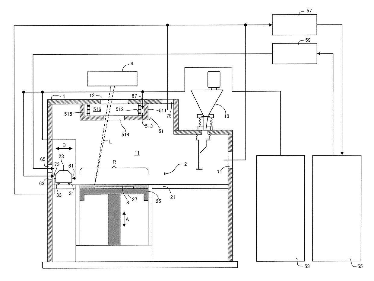
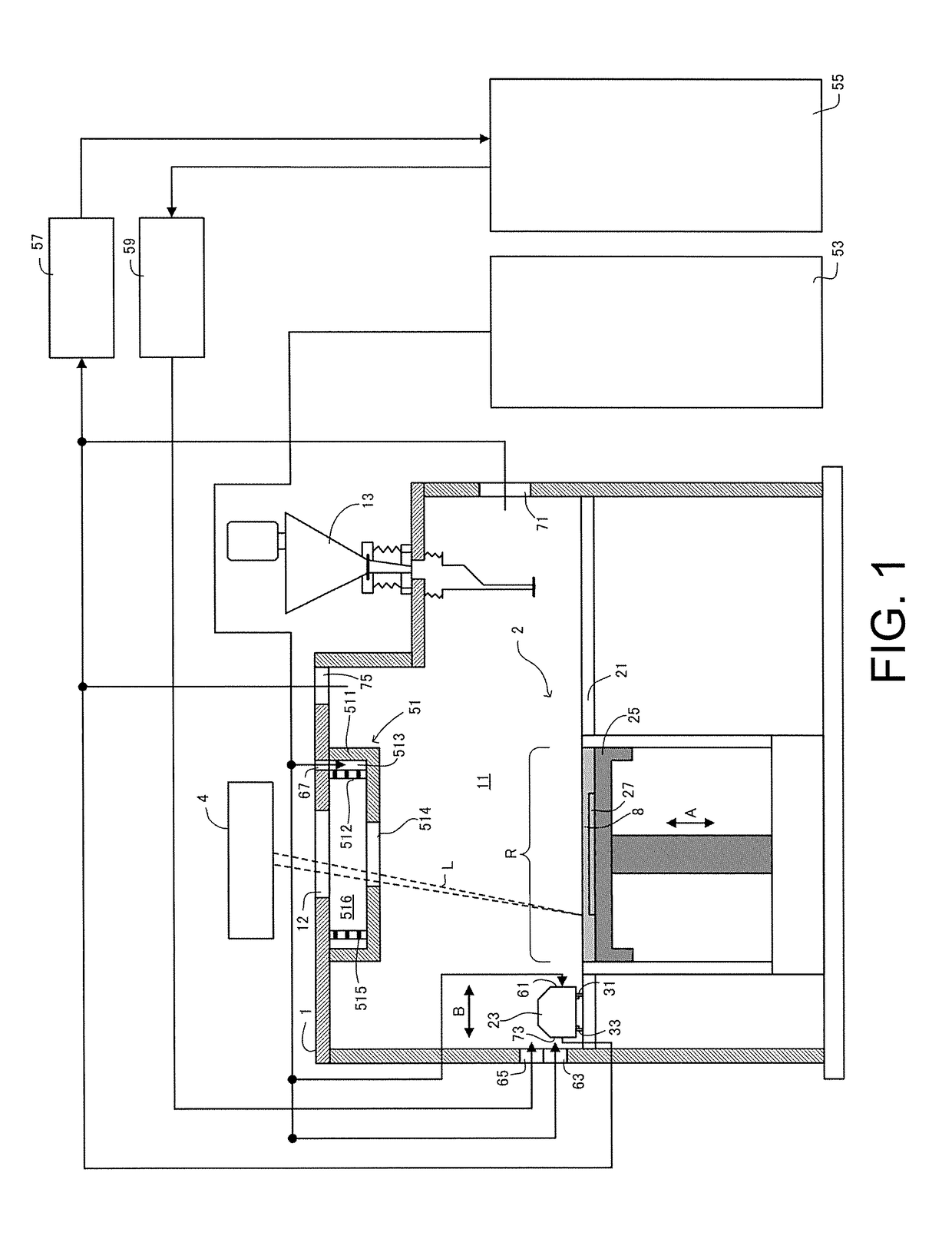
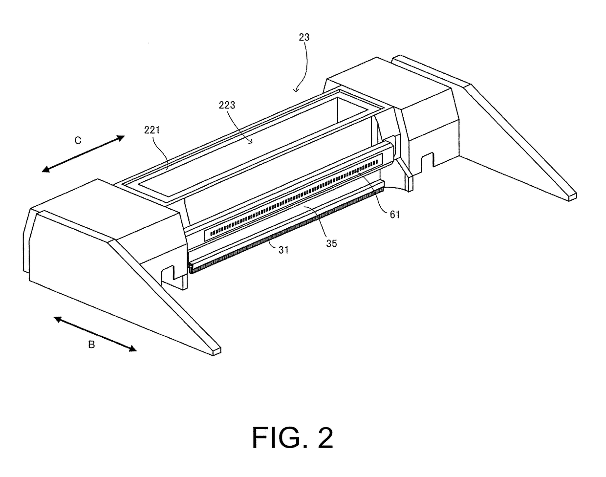
[0026]As shown in FIG. 1, a three-dimensional printer according to an embodiment of the invention includes a chamber 1 configured to be substantially hermetically sealed, and a build chamber 11 is provided inside the chamber 1. A powder layer forming device 2 is provided inside the chamber 1. The powder layer forming device 2 includes a base table 21 having a molding space R in a central penetration portion, a recoater head 23 arranged on the base table 21 and configured to be movable in a horizontal uniaxial direction (direction shown by arrow B), a pair of blades 31 and 33 flattening material powder discharged from the recoater head 23 so as to form a powder layer 8, and a pair of holding members 35 and 37 holding the pair of blades 31 and 33 respectively on the recoater head 23. A table 25 movable in an up-down direction (direc...


PUM

PropertyMeasurementUnit
electrical conductivityaaaaaaaaaa
magnetic susceptibilityaaaaaaaaaa
particle sizeaaaaaaaaaa

Abstract

A three-dimensional (3D) printer includes a powder layer forming device (2) uniformly spreading material powder in a molding space (R) in a chamber (1) to form a powder layer (8), and a laser irradiation device (4) irradiating a laser beam (L) on a predetermined irradiation region of the powder layer to form a sintered layer (9). The powder layer forming device includes a recoater head (23) discharging the contained material powder to the molding space, a blade (31, 33) leveling the discharged material powder to a predetermined thickness, and a holding member (35, 37) holding the blade on the recoater head, wherein the blade is flexible, and the blade and the holding member are nonmagnetic and electrically conductive.

Description

CROSS-REFERENCE TO RELATED APPLICATION[0001]This application claims the priority benefit of Japan Application no. 2016-117862, filed on Jun. 14, 2016. The entirety of the above-mentioned patent application is hereby incorporated by reference herein and made a part of this specification.BACKGROUND OF THE INVENTION[0002]Field of the Invention[0003]The invention relates to a three-dimensional (3D) printer, particularly to a three-dimensional printer which uniformly spreads material powder to sinter a powder layer, and laminates sintered layers to form a molded object.[0004]Description of Related Art[0005]In powder sintering laminate molding method by a laser beam, material powder is uniformly spread on a table to form a powder layer. A laser beam is irradiated on a predetermined portion of the powder layer to sinter the predetermined portion, thereby forming a sintered layer. The material powder is uniformly spread on this sintered layer to form a new powder layer. A laser beam is irra...

Claims


Application Information

Patent Timeline
Patent Type & Authority Patents(United States)
IPC IPC(8): B29C67/00B29C64/153B29C64/214B29K77/00
CPCB29C64/153B29C64/214B29K2077/00B22F2999/00B33Y30/00Y02P10/25B22F10/28B22F12/49B22F12/67B22F12/41B22F12/70B22F10/77B22F2201/10
Inventor MATSUMOTO, ITARU
Owner SODICK CO LTD
Why Eureka
Try Eureka