Tunable ribbon microphone

a ribbon microphone and microphone technology, applied in the field of ribbon microphones, can solve the problems of heavy and enormous ribbon microphones, low current signal output of early ribbon microphones, and dominant footprint of ribbon microphones, and achieve the effect of altering the tension of ribbon

Inactive Publication Date: 2017-10-24
GHAFFARI MOHSEN
View PDF23 Cites 1 Cited by
  • Summary
  • Abstract
  • Description
  • Claims
  • Application Information

AI Technical Summary

Benefits of technology

[0022]In accordance with the present invention, there is provided a tunable ribbon microphone having magnets positioned adjacent with an air gap in between the pieces on opposite poles. An elastic ribbon is placed in the air gap by the adjustable ribbon holder structure. The adjustable ribbon holder structure includes two ribbon holders and a ribbon tension control. One of the ribbon holders can be fixed on one side and the other ribbon holder slides toward the center of the adjustable ribbon holder structure. The ribbon tension control changes the tension of the elastic ribbon. By adjusting the ribbon tension control, rotational motion translates into linear motion and changes the position of the ribbon holders. Accordingly, the change of the distance between the ribbon holders alters the tension of the ribbon. The amount of tension can be measured by the help of measurement bar imprinted on ribbon tension control.

Problems solved by technology

Ribbon microphones have a dominant footprint in recording history, and it has risen and fallen in different periods of time.
Early ribbon microphones have very low current signal output due to the weak magnetic field produced by available magnets at that time.
Because of this, the ribbon microphones were heavy and enormous.
Another issue was the ribbon inside the ribbon microphones.
The ribbons are made of thin aluminum foil that is brittle, and by a blast of air quickly deform and lose tension.
Consequently, the ribbon is put out of place and the microphone starts to generate distortion and loses its original frequency response.
However, the biggest potential of modern day ribbon microphones has not yet been revealed.
In contrast, using conventional microphones involves changing to find the best transducer for the purpose of recording which is time-consuming and in some cases finding the desired result is impossible without using a tunable ribbon microphone.

Method used


Image

  • Tunable ribbon microphone
  • Tunable ribbon microphone
  • Tunable ribbon microphone

Examples


Embodiment Construction

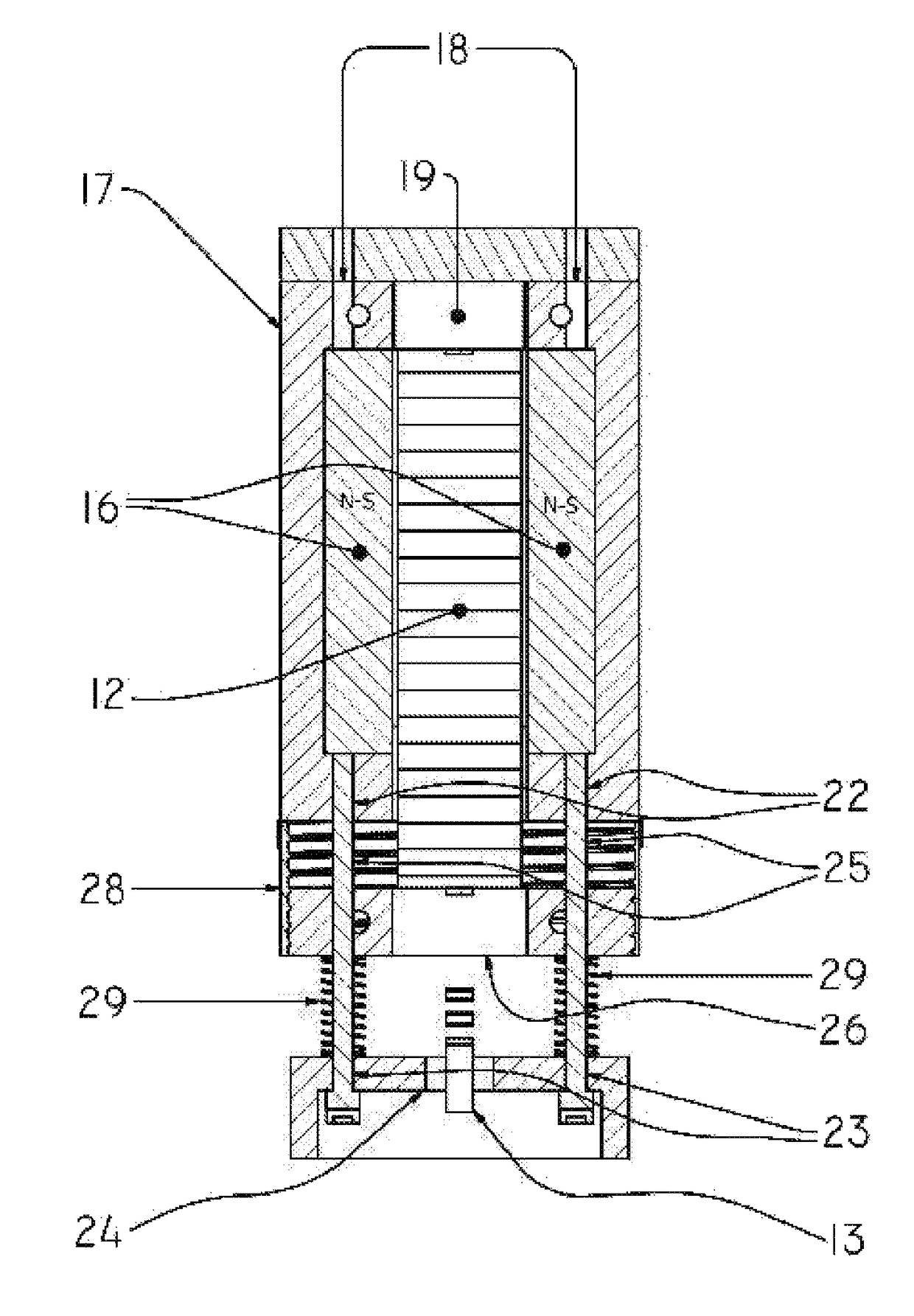
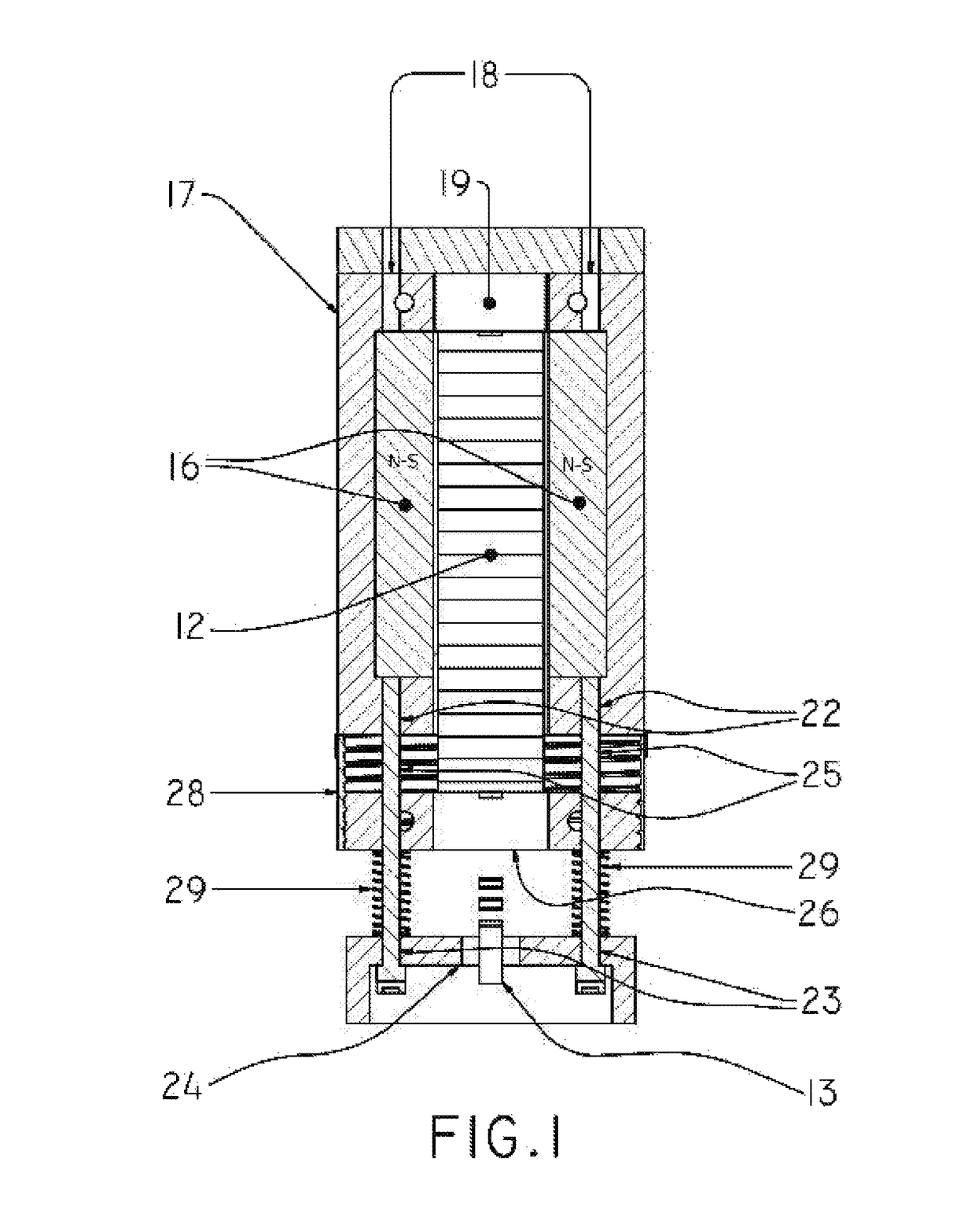
[0034]A tunable ribbon microphone (FIG. 1) is comprised of a magnetic field structure 10 (FIG. 2), adjustable ribbon holder structure 11 (FIG. 3), and a ribbon 12 (FIG. 1). Along with a wiring system 13 (FIG. 4), signal adjustment components and a protection shield.

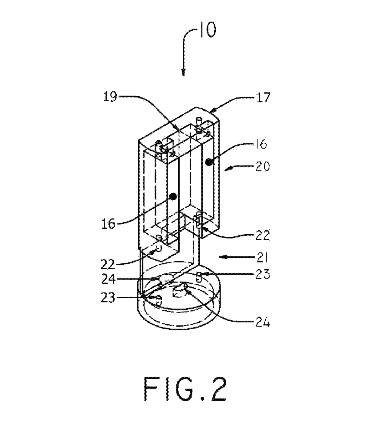
[0035]Referring to FIG. 2 the magnetic field structure 10 provides the required magnetic field for the ribbon 12 to generate sound signals. The magnetic field structure 10 includes magnets 16 and the main body 17 which also serve as a support for the elements of the microphone. There is at least one pair of magnets 16 in parallel and placed on opposite poles to the main body 17 with an air gap in between. The magnets 16 are attached to the main body 17 by any suitable method such as welding or gluing.

[0036]The main body 17 is made of a solid material and includes a fixed ribbon holder 19, magnet placement area 20, adjustable ribbon holder placement area 21; middle body threaded holes 22, lower body holes 23, and wiring ho...


PUM


Abstract

A tunable ribbon microphone having magnets positioned within a small gap in between pieces of opposite poles. A conductive ribbon placed in an air gap between the magnets by an adjustable ribbon holder structure. The adjustable ribbon holder structure includes two ribbon holders and a ribbon tension control. The ribbon holder can be fixed from one side by sliding on one side or sliding on both sides. The ribbon tension control adjusts the tension of the elastic ribbon. By turning the ribbon tension control, turning motion translate to linear motion and change the distance between the ribbon holders and alter the tension of the ribbon. Changing the ribbon tension also possible by different ribbon tension control mechanism by rolled or folded the ribbon in one side or both side of the microphone. The tunable ribbon microphone may have more than one ribbon, adjustable ribbon holder structure and ribbon tension control.

Description

RELATED APPLICATIONS[0001]This application is a 35 U.S.C §371 National Stage of International Patent Application No. PCT / US14 / 65253, field Nov. 12, 2014 which claims benefit of U.S. Provisional Patent Application No. 61 / 907,265, field Nov. 21, 2013.FIELD OF THE INVENTION[0002]The present invention relates to ribbon microphone and, more particularly, to tunable ribbon microphone.BACKGROUND OF THE INVENTION[0003]Ribbon microphones have a dominant footprint in recording history, and it has risen and fallen in different periods of time. In the 1950's the popularity of the ribbon microphones was at its peak.[0004]The ribbon microphones are made with two separate magnets placed in parallel to the opposite poles with an air gap in between to generate a high magnetic field. A thin aluminum foil ribbon is placed in the middle of the magnetic field. The movement of the ribbon generates electrical signals. The signals are increased by a ratio of 1:20 or 1:25 with the use of a transformer.[0005...

Claims


Application Information

Patent Timeline
Patent Type & Authority Patents(United States)
IPC IPC(8): H04R9/04H04R9/08H04R9/02H04R7/22H04R7/18H04R1/22H04R7/14
CPCH04R9/048H04R9/025H04R9/045H04R9/08H04R7/22H04R1/222H04R7/14H04R7/18
Inventor GHAFFARI, MOHSENGHAFFARI, MARYAM
Owner GHAFFARI MOHSEN
Why Eureka
Try Eureka