Router jig for cutting decorative profiles

a technology of routing jigs and decorative profiles, which is applied in the direction of dovetail work, special profiling/shaping machines, profiling/shaping machines, etc., can solve the problems of gap between the ends of the mating sections, difficult to trim either cut end to the correct angle, and difficult to produce neat and accurate joints at corners

Active Publication Date: 2017-10-31
SCRIBE MASTER
View PDF8 Cites 9 Cited by
  • Summary
  • Abstract
  • Description
  • Claims
  • Application Information

AI Technical Summary

Problems solved by technology

When fixing such features around a room or constructing a frame from such sections, it can be difficult to produce neat and accurate joints at corners, with the two profiled sections mating accurately and without a gap between them.
This can result in a gap between the ends of the mating sections, and it can be difficult to trim either cut end to the correct angle.
It has not hitherto been possible to profile such mouldings using a router.

Method used


Image

  • Router jig for cutting decorative profiles
  • Router jig for cutting decorative profiles
  • Router jig for cutting decorative profiles

Examples


second embodiment

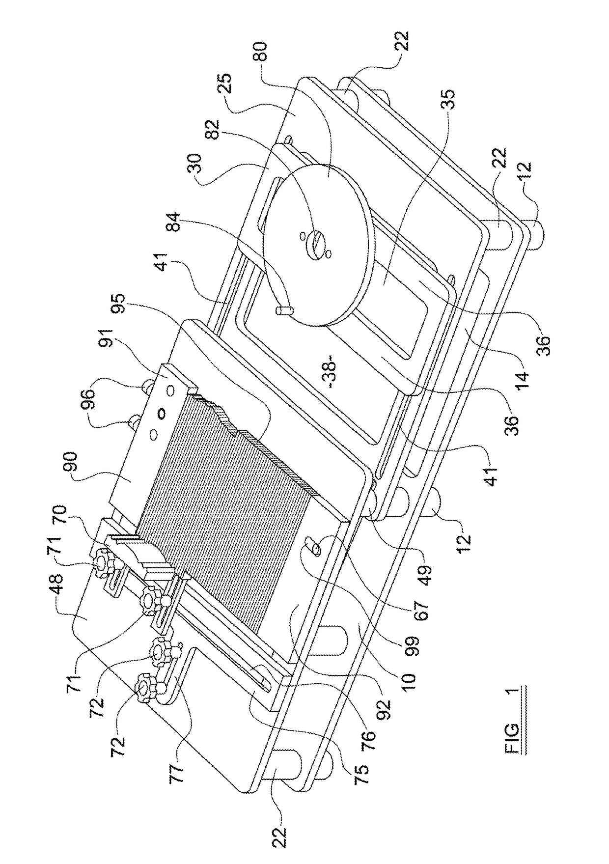
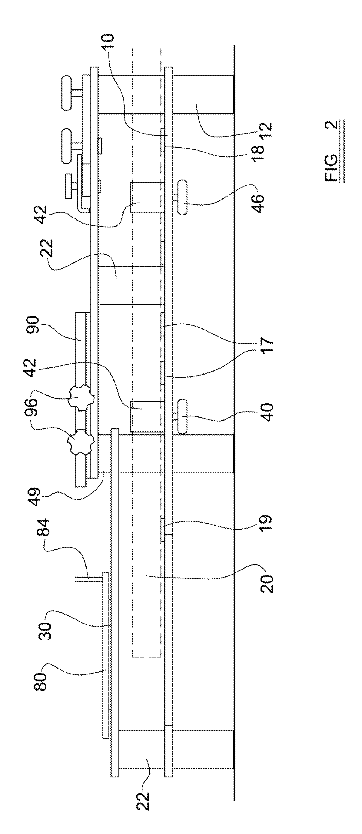
[0074]Turning now to the embodiment of FIGS. 6 to 8, in FIG. 6 a router jig in accordance with the invention differs from the first in that the sample support platform 148 and tool support platform 125 are positioned higher above the base support 110 in order to accommodate coping or crown mouldings such as 170, which need to be cut at an angle. The basic shape of the jig is otherwise essentially similar to that of the embodiments of FIGS. 1 to 5, with the support platforms 125, 148 supported above the base platform on pillars 122, the pillars on one side supporting a workpiece 170. In this case however the workpiece is a crown moulding of the type used to embellish the join between the wall and the ceiling, and in order to mate with a corresponding moulding in the corner of a room the profiling cut needs to be made with the workpiece set at an angle α to the horizontal as shown in FIG. 6. This angle is known as the spring angle, and corresponds to the angle of tilt at which the mou...

first embodiment

[0081]The cutting arrangement is the same as in the embodiment of FIGS. 1 to 5 with a router 210 mounted on a platform 180 arranged to slide onto parallel rungs 136 of a carriage 130, on either side of essential rectangular recess 135 through which the router bit (not shown) can project. The router carriage 130 slides in parallel grooves 141, as in the first embodiment, running on either side of central aperture 138 of the tool support platform 125.

[0082]In this way, the profiled end of the workpiece can be cut along a path corresponding to the spring angle at which the crown mouldings are to be mounted so that the profiled end accurately matches the cross section of the profile that it needs, when set at the desired spring angle.

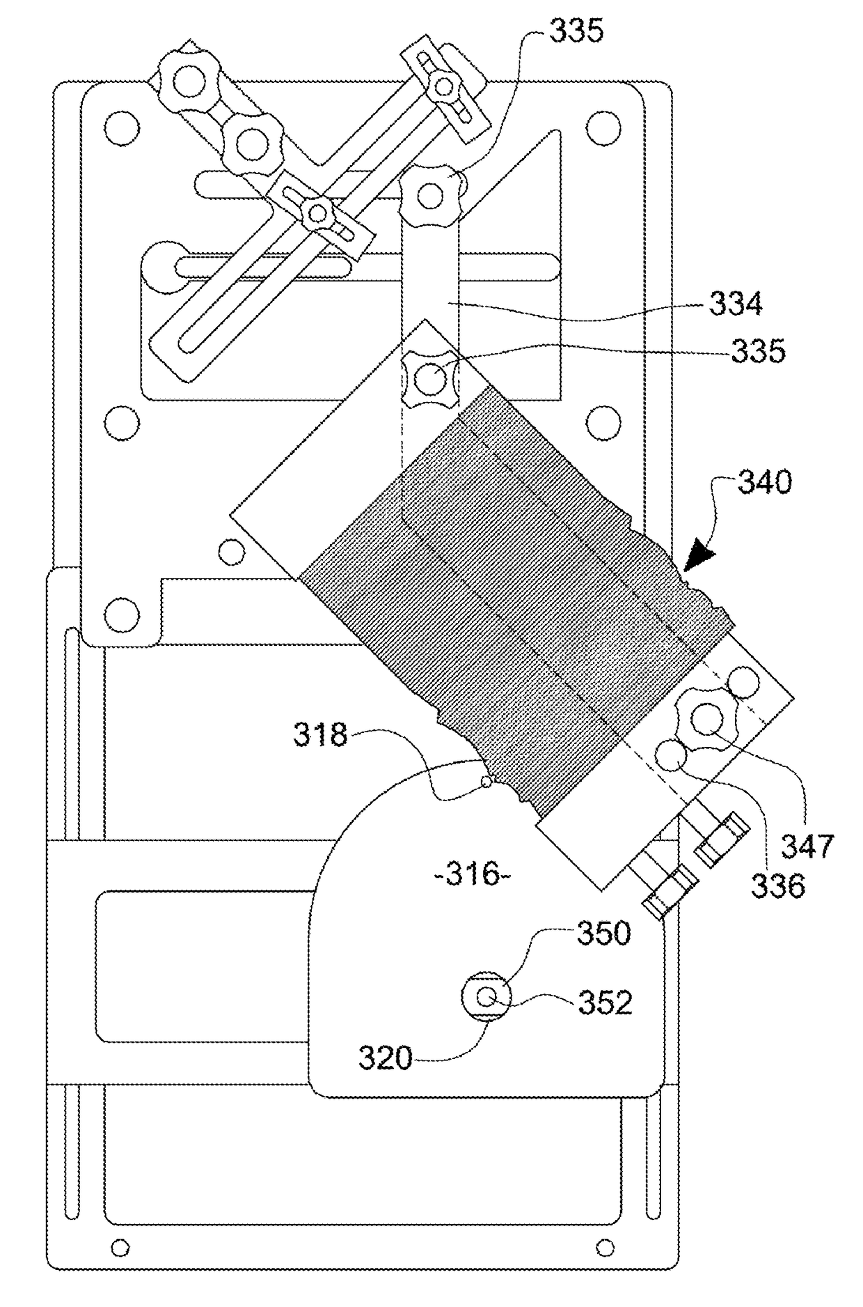
[0083]Turning now to the embodiment of FIGS. 9 to 13, a router jig in accordance with a further embodiment of the invention comprises a flat base 300 on which are mounted a sample support platform 302 and a router carriage support platform 304, both extendi...


PUM


Abstract

A jig for profiling the end of an elongate workpiece, especially a coping or crown molding section, comprises a support for a sample to be copied, and for a profiling comb to be pushed against the sample to define a cam surface. A cutting tool can be mounted to follow a path defined by the cam surface, to cut the workpiece end to match the shape of the cam surface. The profiling comb is movable between a first position facing the sample support to form a profile and a second position in which the profile can contact the cam follower on the movable mounting. In its second position the comb extends at an acute angle to the longitudinal direction of the workpiece support, which is configured to support the workpiece at an acute angle about its longitudinal axis corresponding to the angle at which the comb is fixed.

Description

REFERENCE TO EARLIER APPLICATION[0001]This application claims priority from United Kingdom patent application No. 1309136.8, filed on May 21, 2013, the disclosure of which is incorporated herein by reference.BACKGROUND OF THE INVENTION[0002]Field of the Invention[0003]This invention relates to a jig for guiding a routing tool or the like for cutting the ends of elongate workpieces, and in particular wooden mouldings, to enable accurate joints to be made.[0004]Description of the Prior Art[0005]Skirting boards, picture rails, dado rails, window frame sections and the like are often made with a decorative cross section. When fixing such features around a room or constructing a frame from such sections, it can be difficult to produce neat and accurate joints at corners, with the two profiled sections mating accurately and without a gap between them. If one attempts to cut a 45° mitre joint, it will often be found that the corner in which the two sections meet is not an exact right angle...

Claims


Application Information

Patent Timeline
Patent Type & Authority Patents(United States)
IPC IPC(8): B27C5/10B27C5/00B27F1/00B23Q35/42
CPCB27C5/003B27F1/00B27C5/10B23Q35/42B23Q9/005B23Q35/102
Inventor DAVEY, COLIN ROY
Owner SCRIBE MASTER
Why Eureka
Try Eureka