Crown Molding Cutting Apparatus And Method

a technology of crown molding and cutting apparatus, which is applied in the direction of manufacturing tools, metal sawing devices, precision positioning equipment, etc., can solve the problems of considerable material waste and tim

Active Publication Date: 2008-11-13
NOMIS
View PDF14 Cites 6 Cited by
  • Summary
  • Abstract
  • Description
  • Claims
  • Application Information

AI Technical Summary

Benefits of technology

[0007]The invention provides an improved method and apparatus for positioning a work piece, such as a piece of crown molding, through use of an apparatus including a work piece support plate pivotably attached along a pivot axis to a base which is adapted to rest on a horizontal reference plane, such as the table of a mitre saw, for pivoting motion of the support plate about the pivot axis to...

Problems solved by technology

As anyone who has ever attempted to cut crown molding with a typical mitre saw table and fence arrangement will attest, the entire process can be very confusing and frustrating, and often results in ...

Method used


Image

  • Crown Molding Cutting Apparatus And Method
  • Crown Molding Cutting Apparatus And Method
  • Crown Molding Cutting Apparatus And Method

Examples


exemplary embodiment 100

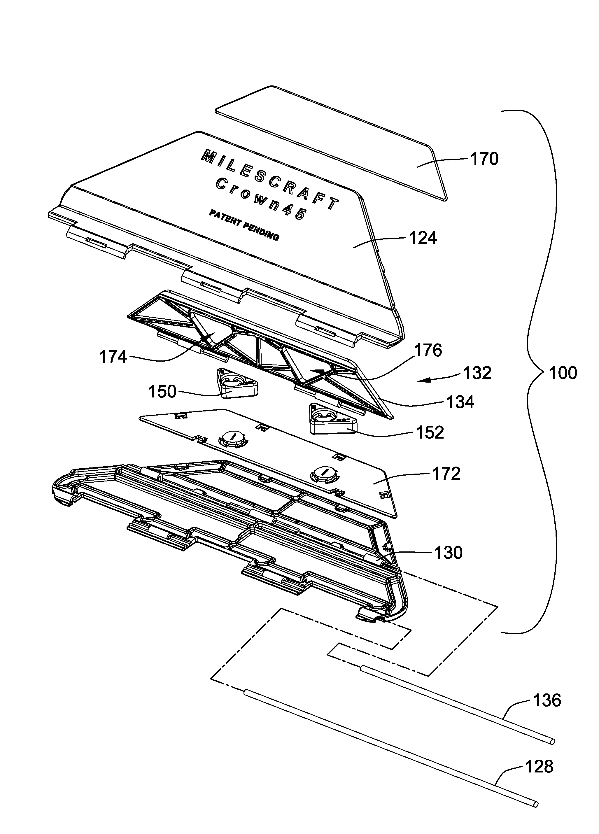
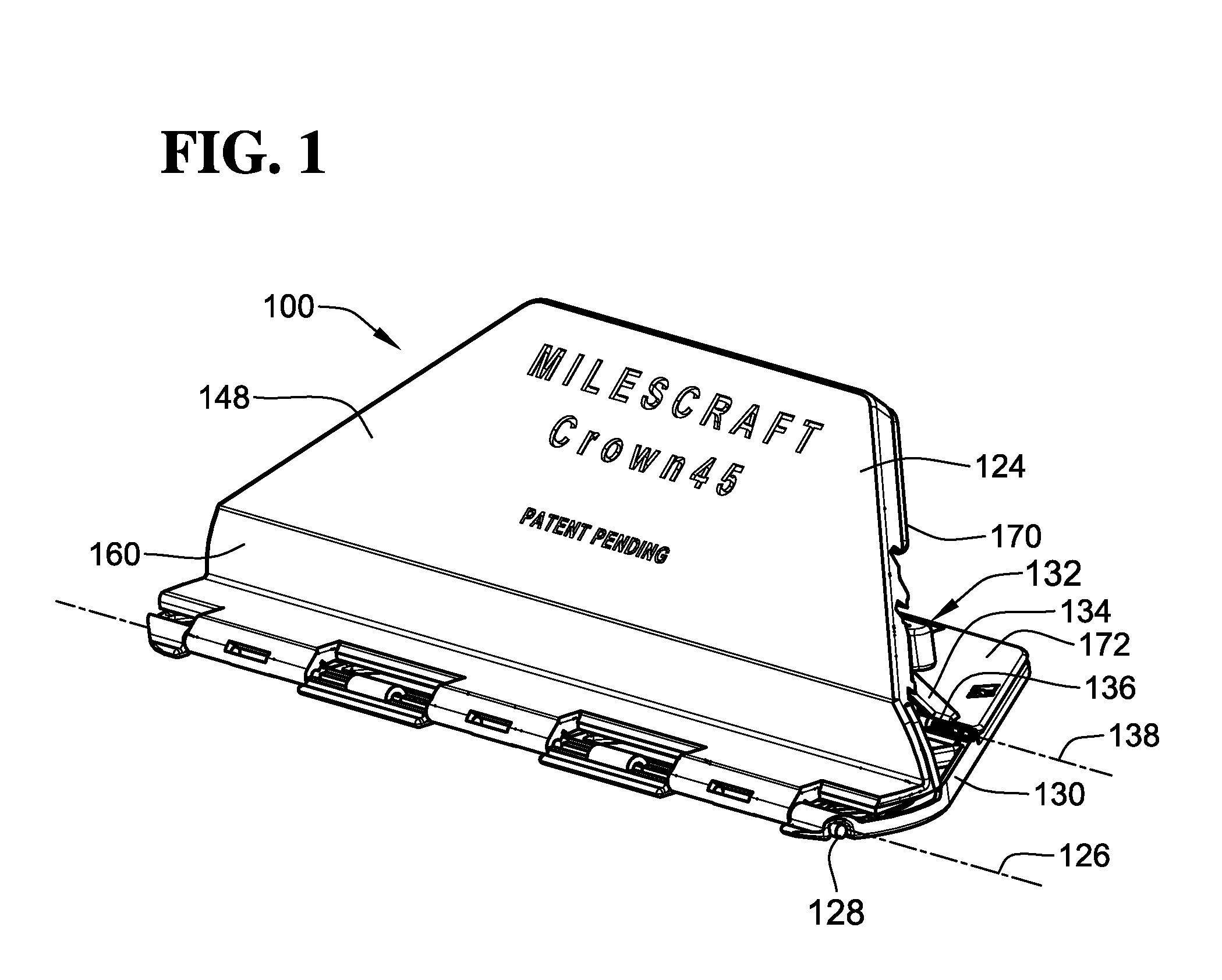
[0045]As shown in FIGS. 8 and 9, in the first exemplary embodiment of the positioning apparatus 100, the brace member 134 is configured to fold flat against the base 130 and the work piece support plate 124 is configured to be pivotable about the pivot axis 126 from any of the desired tilt angles 134 to an angular position adjacent the base 130, for compact stowage of the positioning apparatus 100. As will be understood from an examination of FIG. 5, the brace member 136 of the first exemplary embodiment 100 includes a pair of triangular shaped openings 174, 176 therein which provide clearance around the first and second gage members 150, 152, when the gage members 150, 152 are attached to the base 130, so that the brace member 136 can pivot past the gage members 150, 152 into a folded flat position against the base 130 for stowage.

[0046]FIGS. 10 and 11 illustrate a second exemplary embodiment of a positioning apparatus 200, according to the invention, which is substantially similar...

exemplary embodiment 200

[0051]The insert storage tray 294 is configured to be alternatively attachable to the backside of the support plate 224, in the manner illustrated in FIG. 10, by any appropriate means such as snap interconnections, fasteners, clips or turn-lock retainers. As shown in FIGS. 13 and 14, the storage tray 294, of the second exemplary embodiment 200, is further adapted to be alternatively attached to the support surface 248 of the support plate 224, for stowage within of the inserts 290, 292 when the positioning apparatus 200 is folded for storage, as shown in FIG. 14.

[0052]The exemplary embodiment of the storage tray 294 includes a pair of snap connections 296 at opposite ends of the storage tray 294, which are visible in FIG. 11, for connection of the storage tray 294 to the work piece support plate 224. In addition, a pivoting storage tray connector 298 is pivotably attached to the distal end of the work piece support plate 224, and the storage tray 294 and the storage tray retainer 29...


PUM

PropertyMeasurementUnit
Angleaaaaaaaaaa

Abstract

A method and apparatus are provided, for positioning a work piece, such as a piece of crown molding, through use of an apparatus including a work piece support plate pivotably attached along a pivot axis to a base. The base is adapted to rest on a horizontal reference plane, such as the table of a mitre saw, for pivoting motion of the support plate about the pivot axis to a desired angle with respect to the base, while the pivot axis is simultaneously positioned to extend substantially parallel to a longitudinal line of intersection between a horizontal and a vertical reference plane, established by the table and fence of the mitre saw, to hold the work piece at a desired tilt angle with respect to the vertical reference plane, so that the work piece may be cut in substantially the same orientation as it will be mounted.

Description

CROSS-REFERENCE TO RELATED PATENT APPLICATIONS[0001]This patent application claims the benefit of U.S. Provisional Patent Application No. 60 / 916,529, filed May 7, 2007, the disclosure and teachings of which are incorporated herein, in their entireties, by reference.FIELD OF THE INVENTION[0002]This invention relates to mitre cutting of work pieces, such as crown molding or the like, which are normally installed at an angle from a reference plane, and more particularly to facilitating the cutting of such materials with regard to the table and fence of conventional mitre-type cutting tools in substantially the final installation orientation of the crown molding or the like with respect to its reference surface.BACKGROUND OF THE INVENTION[0003]In order to achieve a pleasing aesthetic appearance, decorative trim pieces, often referred to as crown molding, are sometimes installed at an angle along the intersection of a horizontal and a vertical surface, such as is formed by the ceiling an...

Claims


Application Information

Patent Timeline
IPC IPC(8): B27B27/06B26D5/20
CPCB23D47/04B27B27/08Y10T29/49998B27G5/026B27G5/02Y10T83/8773Y10T83/7697Y10T83/446Y10T83/762
Inventor KOZINA, DAMIAN A.ADKINS, EDWARD D.
Owner NOMIS
Why Eureka
Try Eureka