Eureka AIR delivers breakthrough ideas for toughest innovation challenges, trusted by R&D personnel around the world.

Cutting tool

a cutting tool and cutting blade technology, applied in the direction of metal working apparatus, etc., can solve the problems of uneven or splintered cuts, dust,

Active Publication Date: 2016-09-15
D CUT PROD
View PDF4 Cites 7 Cited by
  • Summary
  • Abstract
  • Description
  • Claims
  • Application Information

AI Technical Summary

Benefits of technology

The present invention provides a portable, non-powered cutting tool that can be used to cut building materials at various angles without splintering or cracking. The blade holder is designed to travel in a straight path, allowing for consistent and repeatable cutting motion. The cutting tool includes a lockable hinge that allows for angling of the cutting surface relative to the base, making it possible to cut building materials with a vertical or angled cut.

Problems solved by technology

Various tools are currently used to cut building materials with a beveled cut, however most are bulky, heavy, require power to be operated, produce large amounts of dust during the cutting process, and / or result in uneven or splintered cuts.

Method used


Image

  • Cutting tool
  • Cutting tool
  • Cutting tool

Examples


Embodiment Construction

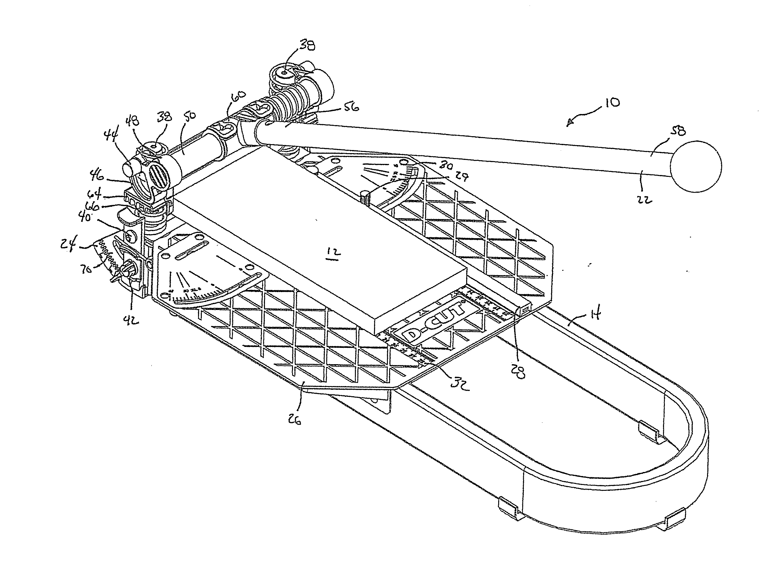
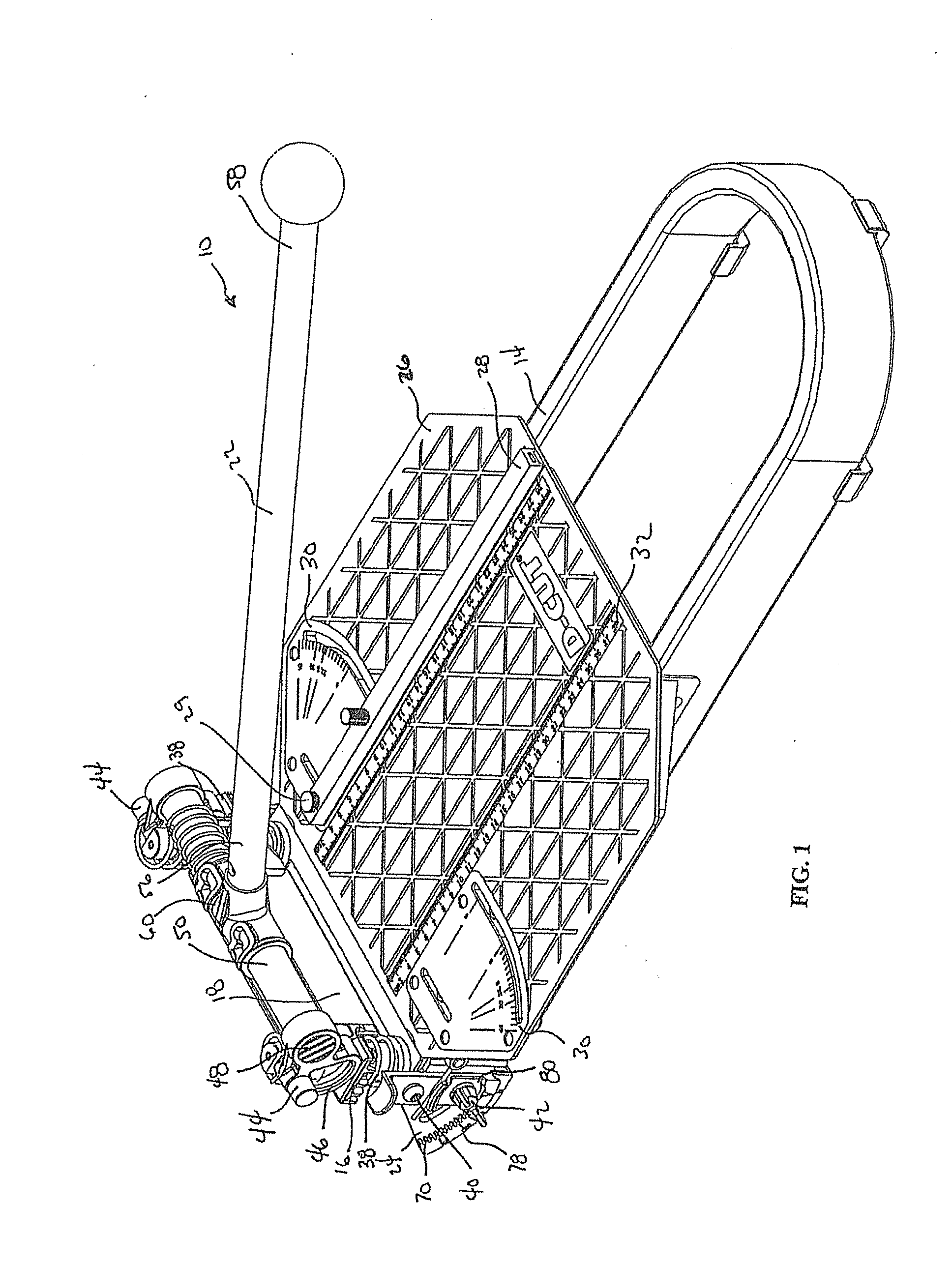
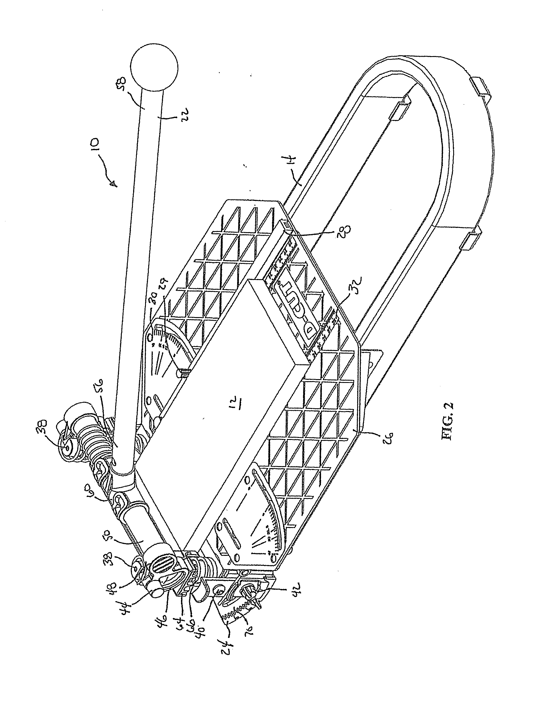
[0057]FIGS. 1 and 2 show a perspective view of a cutting tool 10 according to one embodiment of this invention. The cutting tool 10 as described is preferably used to cut building materials 12, such as laminate, in a predictable and straight fashion without splintering, cracking or similar problems that may arise from such cuts. The cutting tool 10 is capable of cutting the building material 12 at a range of angles from 0°, vertical, to approaching 90°, and preferably ranging from 0° to 60° from vertical. The cutting tool 10 is also capable of cutting the building material at a range of angles in a horizontal plane, ranging from 0°, perpendicular to the blade, to 45° or more. The vertical adjustment allows the cutting tool 10 to cut materials to, for example, fit around or in corners and the horizontal adjustment allows the cutting tool 10 to cut materials to, for example to fit around window or door frames.

[0058]As used herein, “material” refers to a sheet or plank of building mate...


PUM

PropertyMeasurementUnit
Angleaaaaaaaaaa
Angleaaaaaaaaaa
Angleaaaaaaaaaa

Abstract

A cutting tool for cutting flexible building materials, such as, for example, rubber or vinyl baseboards, chair rails and crown molding, at an angle. The cutting tool includes a pair of risers moveably connected near a center of a base with a hinge connection. A blade holder and blade positioned between the risers and moveable from a starting position to a cutting position. The blade can be set to a range of angles relative to the base by rotating the risers and locking the risers in an angle relative to the base.

Description

CROSS REFERENCE TO RELATED APPLICATION[0001]This application is a continuation-in-part of U.S. patent application Ser. No. 15 / 013,349, filed on 2 Feb. 2016, which is a continuation-in-part of U.S. patent application Ser. No. 14 / 613,117, filed on 3 Feb. 2015, which is a continuation-in-part of U.S. patent application Ser. No. 13 / 707,777, filed on 7 Dec. 2012, now U.S. Pat. No. 9,180,600. The co-pending parent application is hereby incorporated by reference herein in its entirety and is made a part hereof, including but not limited to those portions which specifically appear hereinafter.BACKGROUND OF THE INVENTION[0002]1. Field of the Invention[0003]This invention relates to a cutting tool for cutting sheets of building materials, for example laminate, at a range of angles from vertical and / or horizontal including, but not limited to, angles of 22.5°, 45°, 90°, 135°, and 157.5°. More specifically, this invention relates to a cutting tool including a base, a cutting platform adjustably...

Claims


Application Information

Patent Timeline
IPC IPC(8): B26D1/08B26D1/00B26D5/16
CPCB26D1/085B26D2001/004B26D1/0006B26D5/16B26D1/08B26D5/10B26D7/2628Y10T83/762Y10T83/8749Y10T83/8843Y10T83/885B26D1/00B26D7/26
Inventor ZHANG, CHARLIE
Owner D CUT PROD
Why Eureka
Eureka Blog
Learn More