Method and apparatus for pulsed electromagnetic therapy

a pulsed electromagnetic and therapy technology, applied in the field of pulsed electromagnetic therapy, can solve the problems of limited utility in soft tissue trauma treatment, ungainly and difficult application of devices, and difficult use of devices, and achieve the effects of reducing translational stroking motion, extensive treatment site coverage and/or site-specific coverage, and slow magnetic respons

Inactive Publication Date: 2007-02-13
GORDON GLEN A
View PDF24 Cites 77 Cited by
  • Summary
  • Abstract
  • Description
  • Claims
  • Application Information

AI Technical Summary

Benefits of technology

[0022]In another embodiment, the invention may be reconfigured to provide broader magnetic coverage for convenient treatment of larger trauma regions or regions of specific anatomical shape. By using multiple PEMF circuits, each comprising its own field generation and timing circuit, a patterned network of replicated devices may be interconnected to form a surface array. Using appropriate control circuitry, the individual PEMF circuits may be sequentially or simultaneously activated in a cyclic manner to generate the required pulsed waveform, and each PEMF circuit may accordingly provide magnetic field effects in the designated region that it occupies within the array. The collective field effect footprint may be controlled by the spacing and geometric arrangement of the individual PEMF devices within the array, allowing the coverage area to be configured in a

Problems solved by technology

While mostly successful for their intended purpose, difficulty in the use and application of these devices has limited their benefits in the treatment of surrounding soft tissues (e.g., muscles and tendons). field, although a few devices have been developed that use somewhat weaker fields.
As a group, these devices have been ungainly and difficult to apply, especially outside a clinical setting, and consequently have limited utility in treatment of soft tissue traumas.
As was noted above, prior PEMF therapy devic

Method used


Image

  • Method and apparatus for pulsed electromagnetic therapy
  • Method and apparatus for pulsed electromagnetic therapy
  • Method and apparatus for pulsed electromagnetic therapy

Examples


Embodiment Construction

a. Overview

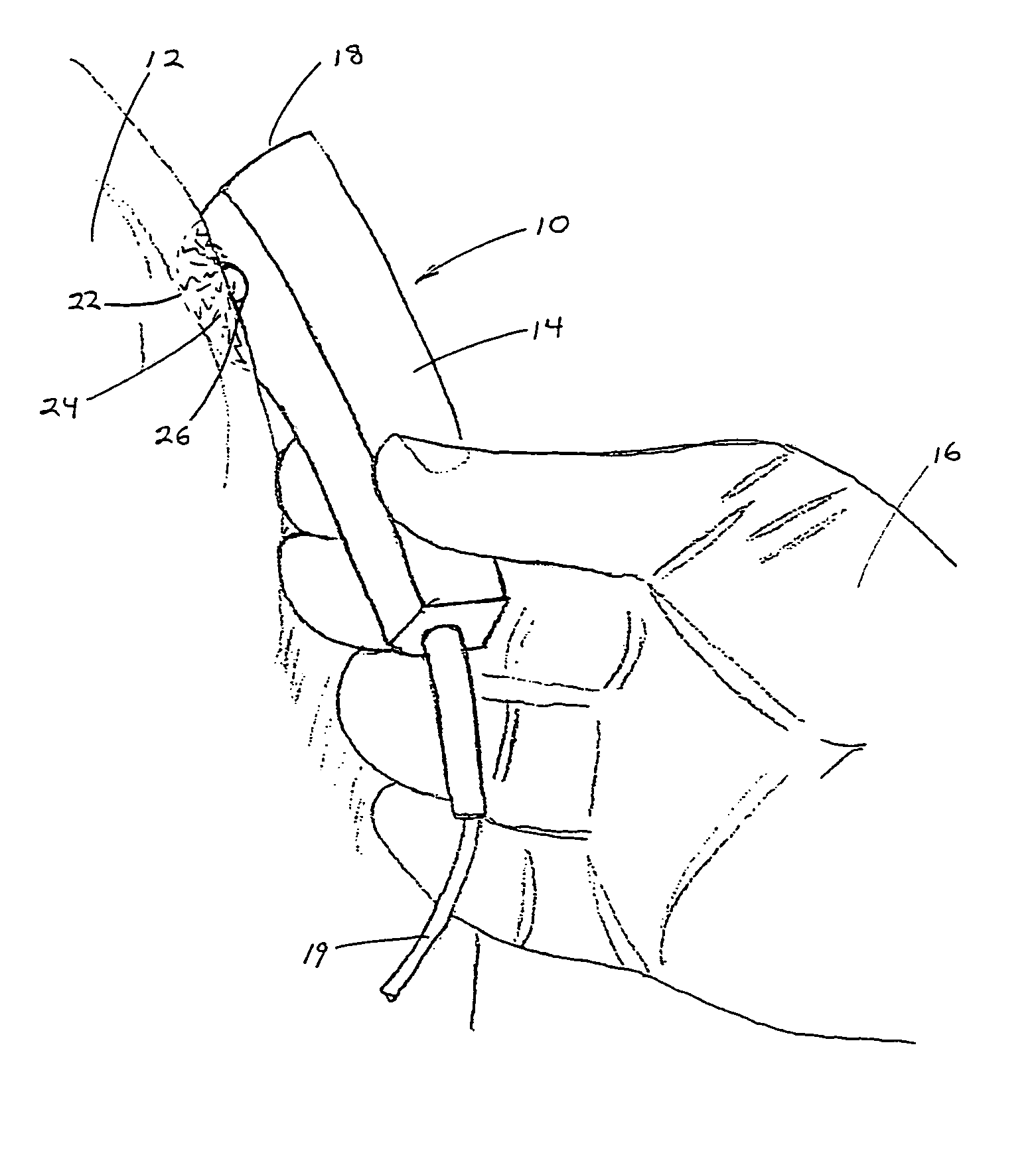
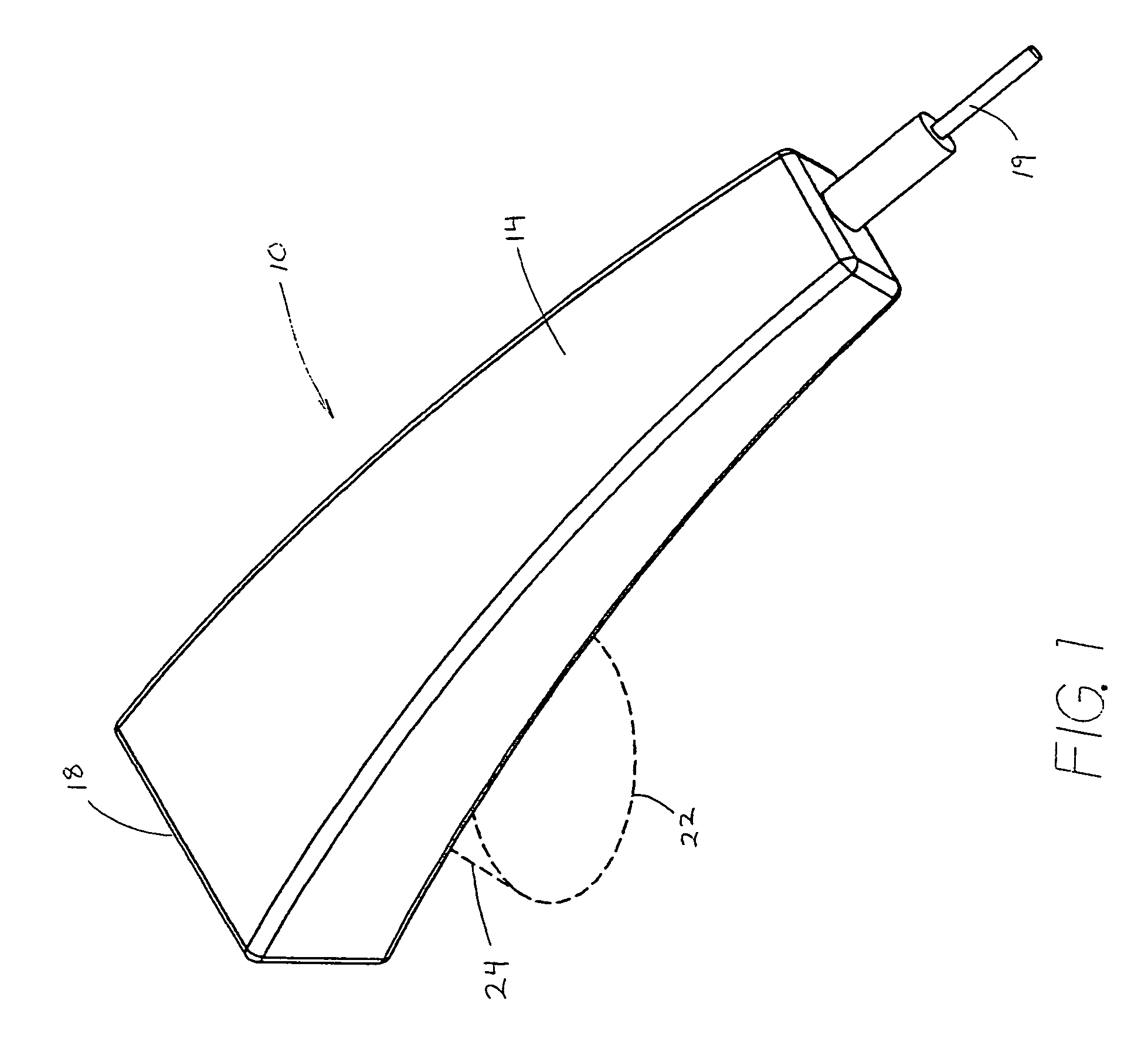
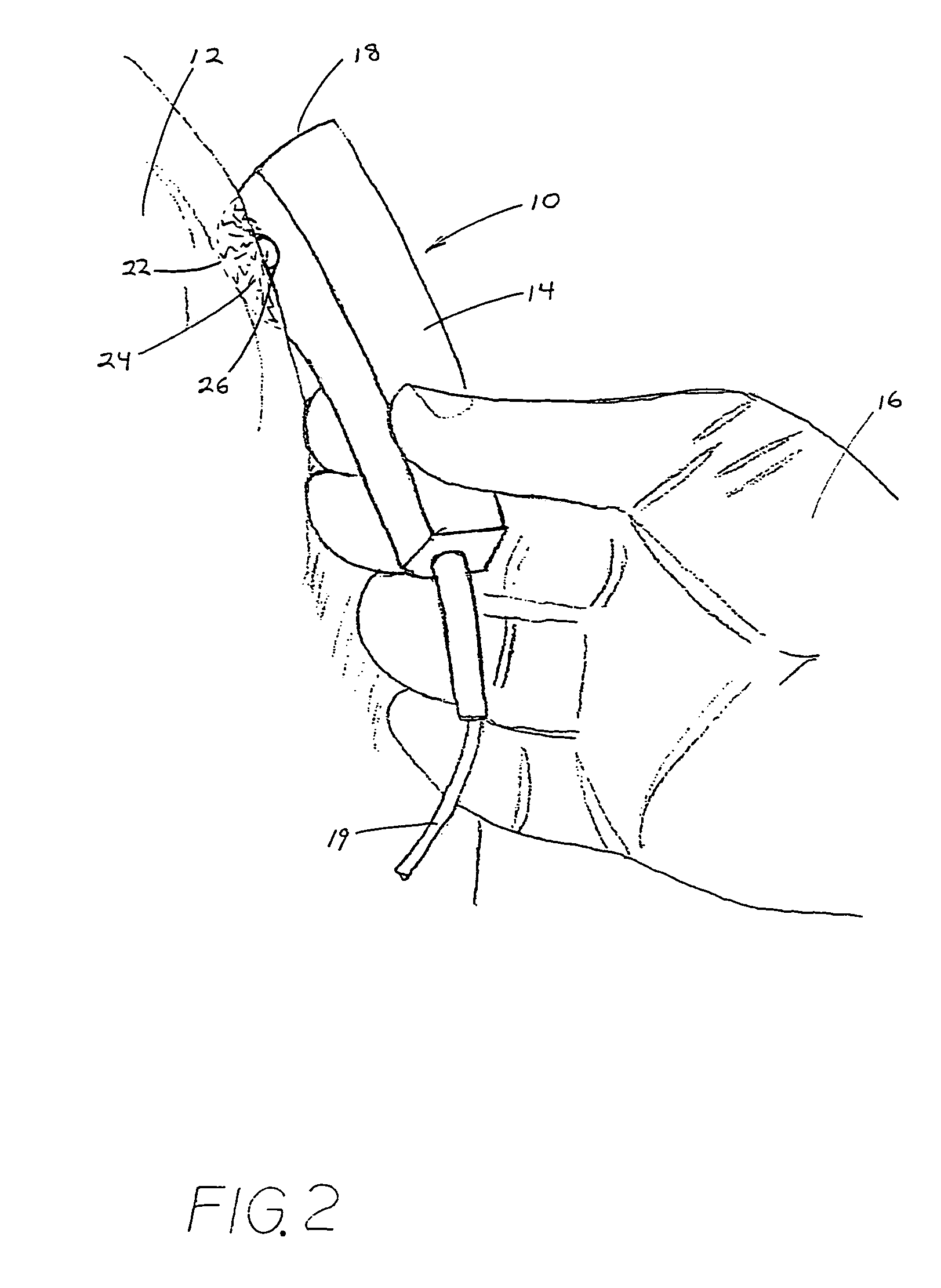
[0030]FIG. 1 provides an isometric overview of a PEMF therapy probe 10 in accordance with a preferred embodiment of the present invention, while FIG. 2 shows the probe being used to treat the knee 12 of a patient. In this preferred embodiment, the device 10 includes a lightweight, compact housing 14 which is easily gripped in the hand 16 of the user for self-application. The housing 14 encloses the functional electronics of the device and may be molded from plastic or fabricated from other suitable materials. In the preferred embodiment, the housing 14 is a commercially available molding made from polymeric material, which helps reduce costs. The functional electronics, including the straight wire element that generates the magnetic field, are integrated on a circuit board (not shown) that is mounted and enclosed within the housing 14 proximate the distal end 18 thereof. Power is supplied to the circuit via transformer by a power cord 19 which is plugged into a standard 1...


PUM


Abstract

An apparatus and method for applying pulsed electromagnetic therapy to humans and animals. A straight wire element is employed to generate the magnetic field. A power and timer circuit supplies current pulses that approximate square pulses in form, so that the straight wire element generates magnetic pulses having rapid rise and fall times. Peak field strength is approximately 2 gauss at a 1 cm distance from the straight wire element, and the duration of peak field strength is approximately 200 nanoseconds. The pulses are repeated at a frequency of about 70 Hz. The straight wire element and circuit may be housed in a hand-held probe, with an LED illuminating the skin area to provide a visual indication of effective range, or a plurality of the straight wire elements and associated circuits may be embedded in a conformable pad that is placed over the affected area of the body.

Description

[0001]This Non-Provisional patent application claims the benefit of prior Provisional Application Ser. No. 60 / 437,247, which was filed 31 Dec. 2002.BACKGROUND OF THE INVENTION[0002]a. Field of the Invention[0003]The present invention relates generally to devices for therapeutic application of magnetic fields, and, more particularly, to a compact, portable device for therapeutic application of weak, pulsed electromagnetic fields for human and animal applications.[0004]b. Related Art and Discussion[0005]The therapeutic value of pulsed electromagnetic fields has gained acceptance through the course of studies and clinical applications. Magnetic fluxes are known to penetrate deeply into human tissue with little attenuation, and have been observed to promote both bone and tissue regeneration. Although the physiological mechanism involved is not fully understood and is the subject of competing hypotheses, it is theorized that magnetic field exposures exert the observed effects through ind...

Claims


Application Information

Patent Timeline
IPC IPC(8): A61N2/00A61N2/02A61N2/04
CPCA61N2/02
Inventor GORDON, GLEN A.HAUEISEN, DONALD C.
Owner GORDON GLEN A
Why Eureka
Try Eureka