Broadband Multifunction Airborne Radar Device with a Wide Angular Coverage for Detection and Tracking, Notably for a Sense-and-Avoid Function

Active Publication Date: 2011-06-30
THALES SA
View PDF14 Cites 53 Cited by
  • Summary
  • Abstract
  • Description
  • Claims
  • Application Information

AI Technical Summary

Benefits of technology

[0024]One advantage of the invention is that it makes it possible to obtain a device, which forms the subject matter thereof, with a wide angular coverage in standby mode, with a high rate, without impairing the performance of the target tracking function.
[0025]Another advantage of the invention is that it allows the addition of related functions allowing greater functional compactness, such as bird collision prevention, weather detection, help in detecting atmospheric conditions, such as icing, and a beacon function for automatic landing gear.
[0026]Another advantage of the invention is that it is very tolerant to breakdowns.
[0027]For this purpose, one subject of the invention is a multifunction airborne radar device operating in active and passive modes, characterized in that it comprises a plurality of antenna modules fixed relative to the aircraft, which are placed substantially on the surface of the aircraft and form transmit and receive beams of width adapted to the aimed direction, allowing detection of targets for the implementation of a sense-and-avoid function.
[0028]In one embodiment of the invention, the antenna modules may be transmit and / or receive antenna modules.
[0029]In one embodiment of the invention, the antenna modules may comprise a plurality of individual receive channels and / or radiating elements.

Problems solved by technology

A sense-and-avoid system may present a risk with respect to the safety of personnel and must consequently meet stringent requirements in terms of reliability and effectiveness.
Furthermore, such systems have the drawback of requiring an excrescence on the structure of the drone, accommodating the motorized or electronic scanning antenna structure.
This drawback entails aerodynamic and / or size constraints.
Since the antenna structure is centred thereat, an impact on the nose of the aircraft may then entail a complete loss of the sense-and-avoid function.
The redundancy of such a system is also tricky, if not impossible, to realize in practice.
Another drawback of the known systems of the prior art lies in the fact that they do not allow a plurality of functions to be carried out on the basis of the same physical architecture.
Now, the Ka-band for example does not enable weather conditions to be detected, narrow-beam or scanning radars not being able to carry out more than one function simultaneously.
Thus, a scanning radar does not allow for a weather radar, itself operating in scanning mode, to be reliably detected since the probability of intercepting the signals is low.
Another drawback of the known systems of the prior art also lies in the fact that antenna scanning entails a relatively low probability of detecting obstacles.
Moreover, the known systems of the prior art cannot hierarchize the danger level of the detected targets.
In these systems, the target tracking can be carried out only in sampled mode, with the consequence of there being a risk of confusion, mainly in the presence of ground clutter, or else of ground vehicles.
These systems focus onto particular targets, by switching from a standby mode to a tracking mode, but such switching nevertheless impairs the detection of potentially hazardous new targets.
Thus, multi-target tracking is limited by the mechanical constraints on the antenna.
Such tracking may be implemented at very high scanning rates, for example with scanning times of less than two seconds, but this means a short integration time on the target and requires the use of high transmission power levels.
Consequently, in the systems known from the prior art, since the refresh times are long and the integration time on the target is short, it is not possible for the receive channel to alleviate the deficiencies associated with scanning.
The transmission power levels necessary for accomplishing the sense-and-avoid function are therefore high, with the following drawbacks:high power consumption;the necessity of operating the radar in pulsed mode;the necessity of using higher operating frequencies, for the purpose of allowing satisfactory spatial segregation, to the detriment of efficiency;the difficulty of ensuring effective heat dissipation, since the transmitter is centralized;the necessity of typically dedicating the nose of the aircraft to implementing the sense-and-avoid function;the difficulty of providing satisfactory immunity to electromagnetic radiation, because of the high transmission power;the difficulty of making a system based on moving components of major criticality reliable;antenna scanning has the consequence that targets are tracked discontinuously, these being sampled at the scanning rate.
It is also necessary to associate, with each scan, the detected echoes with the corresponding tracks, even during turns by the carrier, except if the inertial guidance system of the latter is integrated into the tracking system, the inertial guidance system then being critical for the sense-and-avoid function;the limitations inherent in multi-target tracking, notably the limitation on the number of tracks followed, and the necessity of operating specific antenna pointing means; andthe necessity for a long illumination time for targets having a low radar cross section or RCS, making it difficult to achieve a good compromise between the data refresh rate and the quality of the tracking.
Known systems of the prior art for providing a sense-and-avoid function may also be based on cooperative modes; however such systems have the following drawbacks:small private planes, powered ultra-lights, delta wings and balloon probes are not equipped with cooperative means; andin dense traffic zones, the existing standards relating to cooperative modes impose avoidance procedures on aircraft by a change of altitude, yet aircraft of the drone type may be incapable of sudden changes of altitude, because of a lack of engine power and because their aerodynamic finesse does not allow them to ascend or descend rapidly.

Method used


Image

  • Broadband Multifunction Airborne Radar Device with a Wide Angular Coverage for Detection and Tracking, Notably for a Sense-and-Avoid Function
  • Broadband Multifunction Airborne Radar Device with a Wide Angular Coverage for Detection and Tracking, Notably for a Sense-and-Avoid Function
  • Broadband Multifunction Airborne Radar Device with a Wide Angular Coverage for Detection and Tracking, Notably for a Sense-and-Avoid Function

Examples


Embodiment Construction

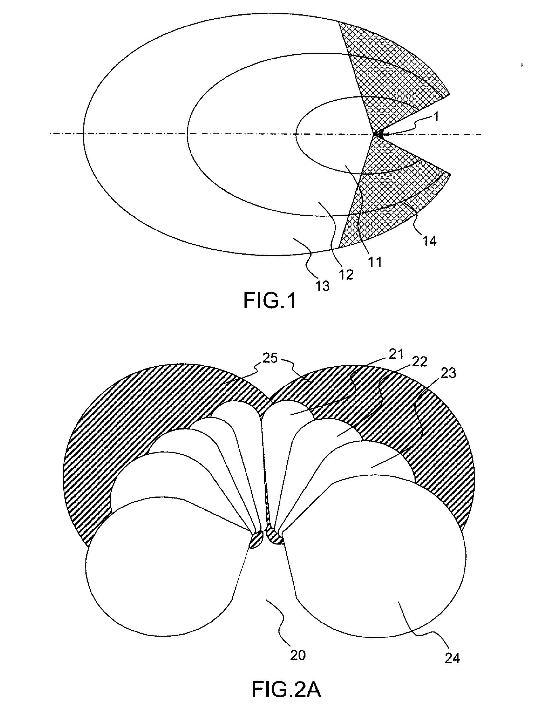
[0064]FIG. 1 shows, as a top view, the various detection zones for an aircraft provided with a sense-and-avoid function.

[0065]An aircraft 1 is flying in an airspace, and the detection system associated with it must cover a plurality of detection zones 11, 12, 13 within which the detection of targets entails different actions requiring different reaction times.

[0066]The first detection zone 11 is defined closest to the aircraft 1, and the representation of the first detection zone 11 in the principal plane of the aircraft 1 may be an ellipse, one of the foci of which coincides with the aircraft 1. Any detection of a target within the first detection zone 11 is considered to be an immediate hazard and an immediate reaction of the aircraft 1 is required, for example to undertake an automatic avoidance procedure.

[0067]The second detection zone 12 is defined, with reference to the aircraft 1, in a spatial field located beyond the first detection zone 11. The representation of the second ...


PUM


Abstract

A multifunction airborne radar device includes a plurality of transmit antenna modules and / or receive antenna modules that are fixed relative to the aircraft, placed substantially over the surface of the aircraft so as to form transmit and receive beams, enabling targets to be detected for implementing a sense-and-avoid function. The airborne radar device may also comprise processing means for tracking the detected targets and for generating information sent to an air traffic control centre and / or to a control device on board the aircraft. The processing device may also receive data relating to the aircraft, enabling the antenna beams to be adjusted and the tracking calculations to be refined.

Description

CROSS-REFERENCE TO RELATED APPLICATIONS[0001]This application claims priority to foreign France patent application No. 0904224, filed on Sep. 4, 2009, the disclosure of which is hereby incorporated by reference in its entirety.TECHNICAL FIELD[0002]The present invention relates to a broadband multifunction airborne radar device with a wide angular coverage for detection and tracking for a sense-and-avoid function. It applies notably to the field of airborne radars and more particularly to the field of radars for implementing a sense-and-avoid function.BACKGROUND[0003]Pilot-assisted air vehicles, or even unmanned air vehicles or UAVs, also known as “drones”, presently fly in segregated zones. However, ATC (air traffic control) airspace, in which notably civil aircraft fly, is set to become populated by an increasing number of vehicles of the aforementioned types. It is consequently necessary for these aircraft to be able to fly in all classes of air space, and to cross frontiers, with...

Claims


Application Information

Patent Timeline
Patent Type & Authority Applications(United States)
IPC IPC(8): G08G5/02G01S13/93G01S13/933G01S13/935
CPCG01S13/913G01S13/953G01S13/94G01S13/9303G01S13/935G01S13/933Y02A90/10
Inventor GARREC, PATRICKCORNIC, PASCALKEMKEMIAN, STEPHANE
Owner THALES SA
Why Eureka
Try Eureka