Crown molding ruler

a technology of crown molding and ruler, which is applied in the field of crown molding ruler, finish carpentry, etc., can solve the problems of crown molding being installed by an artisan probably the most difficult task in the building industry, and the cutting accuracy suffers with the “stand-up” system

Inactive Publication Date: 2011-11-17
GLOMB SR TIMOTHY J
View PDF0 Cites 8 Cited by
  • Summary
  • Abstract
  • Description
  • Claims
  • Application Information

AI Technical Summary

Problems solved by technology

“The installation of crown molding is probably the most difficult task for an artisan in the building industry.
Cutting accuracy suffers with the “stand-up” system.

Method used


Image

  • Crown molding ruler
  • Crown molding ruler
  • Crown molding ruler

Examples


Embodiment Construction

Crown Molding Ruler

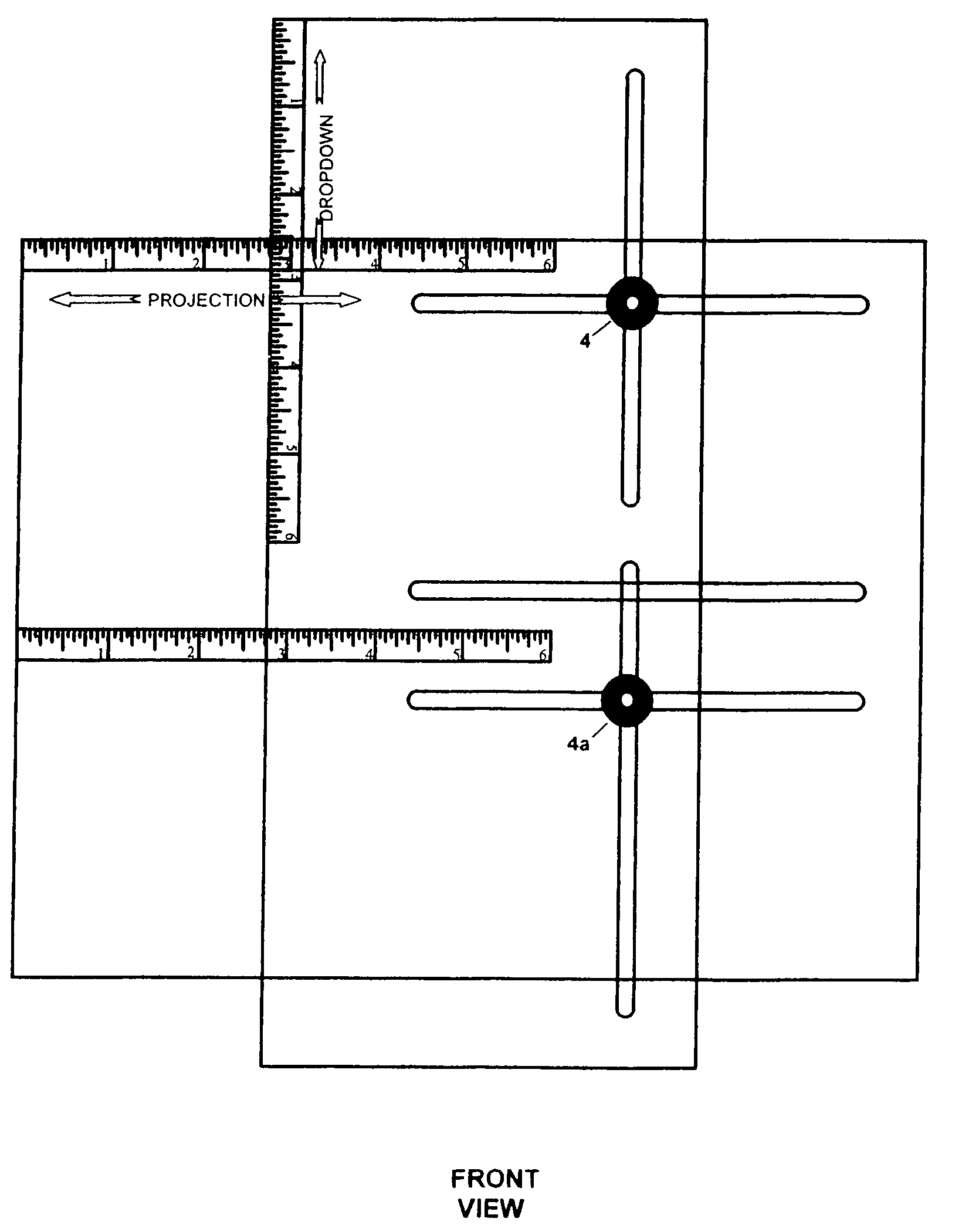
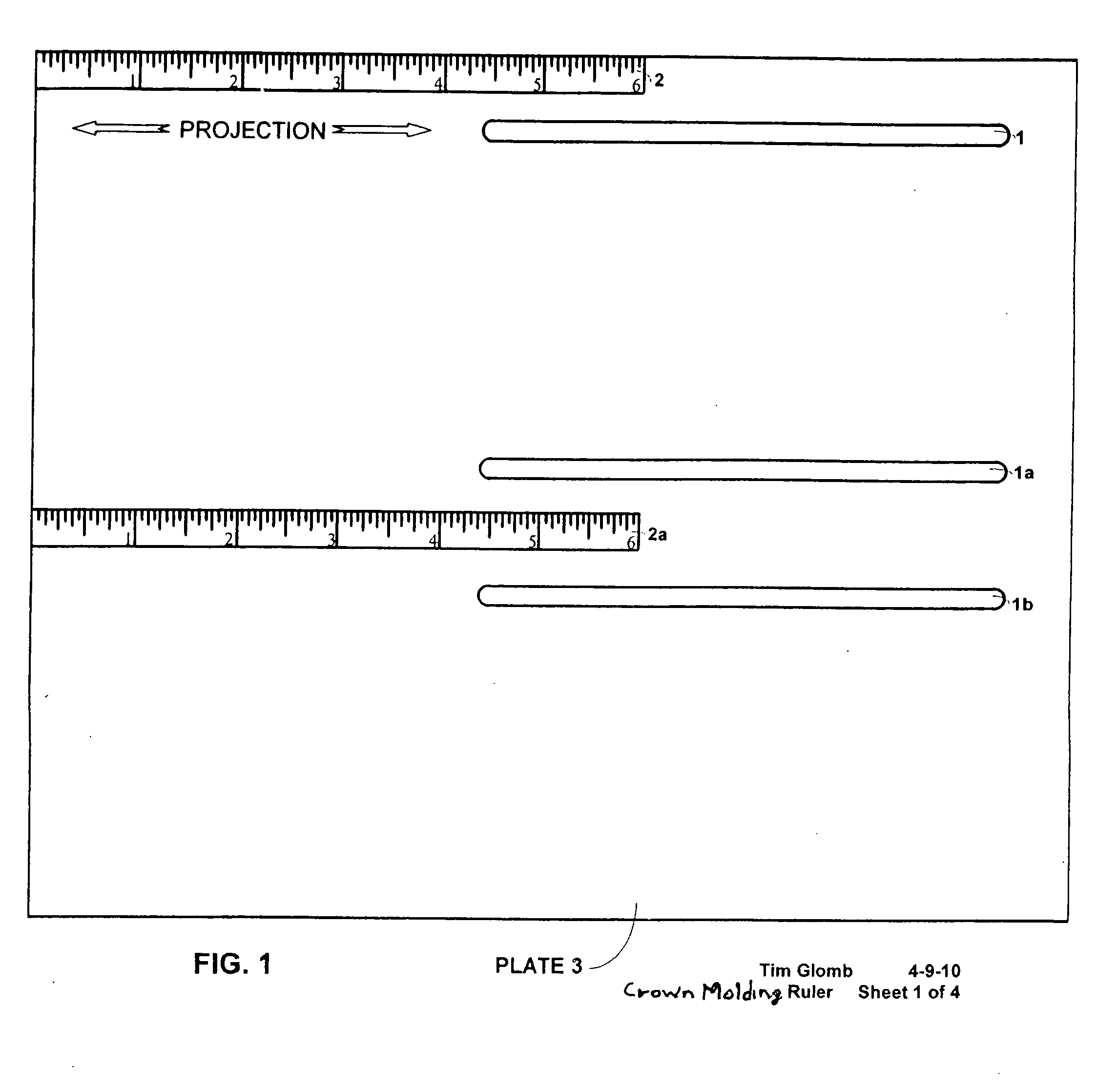
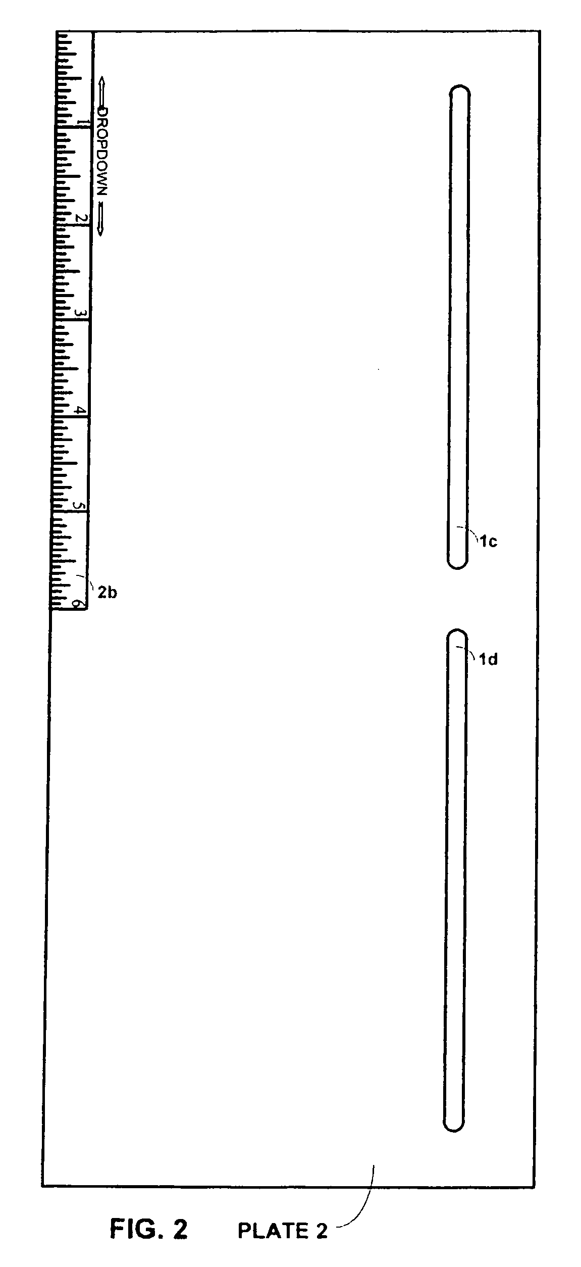
[0017]The invention is comprised of two rectangular flat plates. “Plate 3” measures 8.5″×10.25″×0.10″, it has three slots 1, 1a, 1b (0.1875″×5.5″ long) parallel to each other routed out lengthwise in the surface, and it has a 6″ long measuring scale 2 on the top edge from the left corner to the right, and a 6″ long measuring scale 2a extending from left to right just under the center of the plate. “Plate 2” measures 5″×12″×0.10″, it has two slots 1c, 1d (0.1875″×4.875″ and 0.1875″×5.125″) inline 0.625″ apart routed out lengthwise in the surface, it has a 6″ long measuring scale 2b on the left edge from the top corner down. Plate 2 is placed on top of Plate 3 with the slots perpendicular to each other. A ⅛″×½″ truss head screw 3 is placed into the top slot of Plate 3 and through the top slot of Plate 2. Another ⅛″×½″ truss head screw 3a is placed into the bottom slot of Plate 3 and through the bottom slot of Plate 2. A knurled nut 4, 4a is placed on the end of each...


PUM


Abstract

The present invention provides an apparatus and method for measuring and / or marking simultaneously the projection dimension and the dropdown dimension of crown molding.

Description

CROSS-REFERENCE TO RELATED APPLICATIONS[0001]This applications claims benefits of Provisional Application for Patent No. 61 / 395,508, filed May 14, 2011, applicant—Timothy J. Glomb, Sr., Kennett Square, Pa.STATEMENT REGARDING FEDERALLY SPONSORED RESEARCH OR DEVELOPMENT[0002]“Not Applicable”REFERENCE TO A SEQUENCE LISTING, A TABLE, OR A COMPUTER PROGRAM, LISTING COMPACT DISC APPENDIX[0003]“Not Applicable”BACKGROUND OF THE INVENTION[0004]The present invention is directed towards a tool for use with construction projects. Although the invention may be used in many fields, it has particular relevance to the field of finish carpentry, specifically installing crown molding in a room, and will be discussed with respect thereto. Crown molding is a decorative molding used in many areas including placement along the corner of a room where the top of a wall meets the ceiling at a right angle. This area will be used for description.[0005]Crown molding is made of wood or other synthetic material ...

Claims


Application Information

Patent Timeline
Patent Type & Authority Applications(United States)
IPC IPC(8): G01C15/10
CPCG01B3/04G01B3/566G01B3/08
Inventor GLOMB, SR., TIMOTHY J.
Owner GLOMB SR TIMOTHY J
Why Eureka
Try Eureka