Installation bracket and system for crown molding

a technology of installation bracket and crown molding, which is applied in the direction of walls, floors, building components, etc., can solve the problems of inability to adjust the positioning of the crown molding by the installer, the decorative face of the crown molding is often marred, and the installation of a length of crown molding along the junction of wall and ceiling surfaces requires considerable amount of expertise and patience, so as to shorten the length of the back member

Inactive Publication Date: 2011-04-19
DE RAUCOURT JEAN CLAUDE
View PDF8 Cites 8 Cited by
  • Summary
  • Abstract
  • Description
  • Claims
  • Application Information

AI Technical Summary

Benefits of technology

[0010]In a further embodiment of the present invention, the backing member has a front surface and a back surface, each of the front and back surfaces formed with a plurality of segments defined by spaced apart segment lines, portions of the backing member being adaptable for snapping along the spaced apart segment lines to shorten the length of the back member.

Problems solved by technology

The installation of a length of crown molding along the junction of wall and ceiling surfaces requires a considerable amount of expertise and patience, especially when minute adjustments to the positioning of the crown molding are required to properly install the molding along the wall and ceiling surfaces.
Once fastened to the surface using the concrete screws, the positioning of the crown molding cannot be adjusted by the installer without unfastening the entire length of crown molding from the wall and ceiling surfaces and pre-drilling new holes in the desired location in the concrete wall.
Given the larger diameter of most crown molding fasteners, including concrete and dry wall screws, the decorative face of the crown molding commonly becomes marred as a result of the fastening and unfastening of the plurality of fasteners along the length of the crown molding.

Method used


Image

  • Installation bracket and system for crown molding
  • Installation bracket and system for crown molding
  • Installation bracket and system for crown molding

Examples


Embodiment Construction

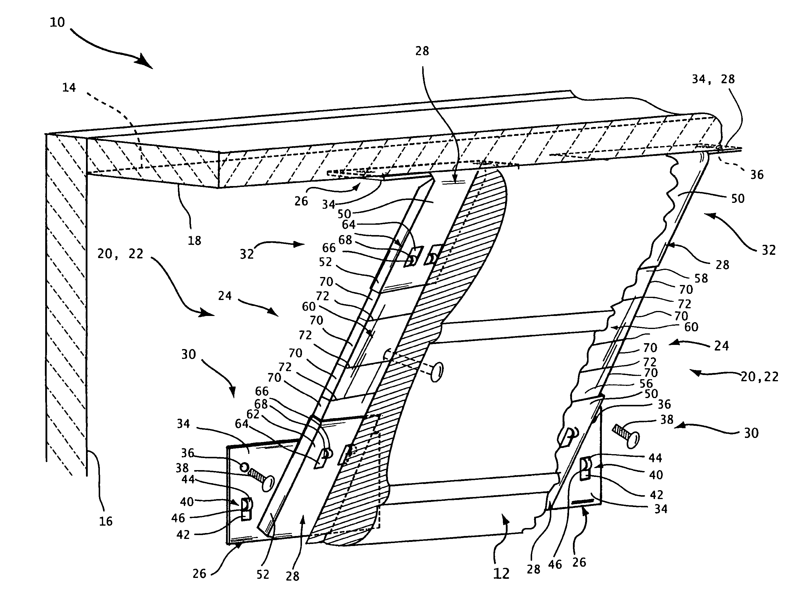
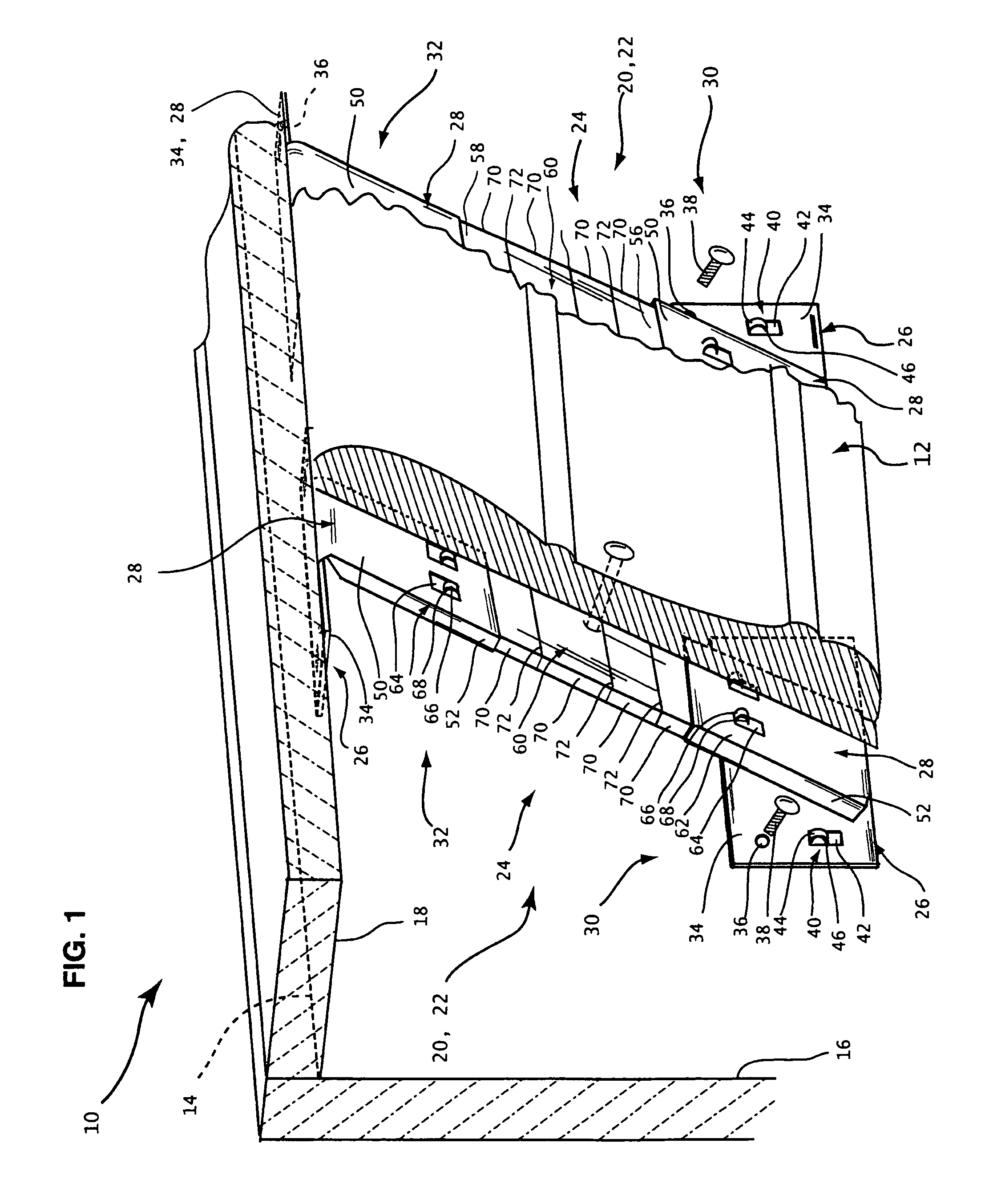
[0018]Referring now to the drawings there is shown generally as reference number 10 an installation bracket system constructed in accordance with the present invention for securing a length of decorative crown molding 12 adjacent to a junction 14 between a wall surface 16 and a ceiling surface 18 to enhance the aesthetic appearance of the interior design of commercial and residential buildings. The installation bracket system 10 of the present invention is designed to facilitate the installation of crown molding 12 on a wide variety of wall and ceiling surfaces 16 and 18, including surfaces constructed from wood, steel, dry wall or form-poured concrete.

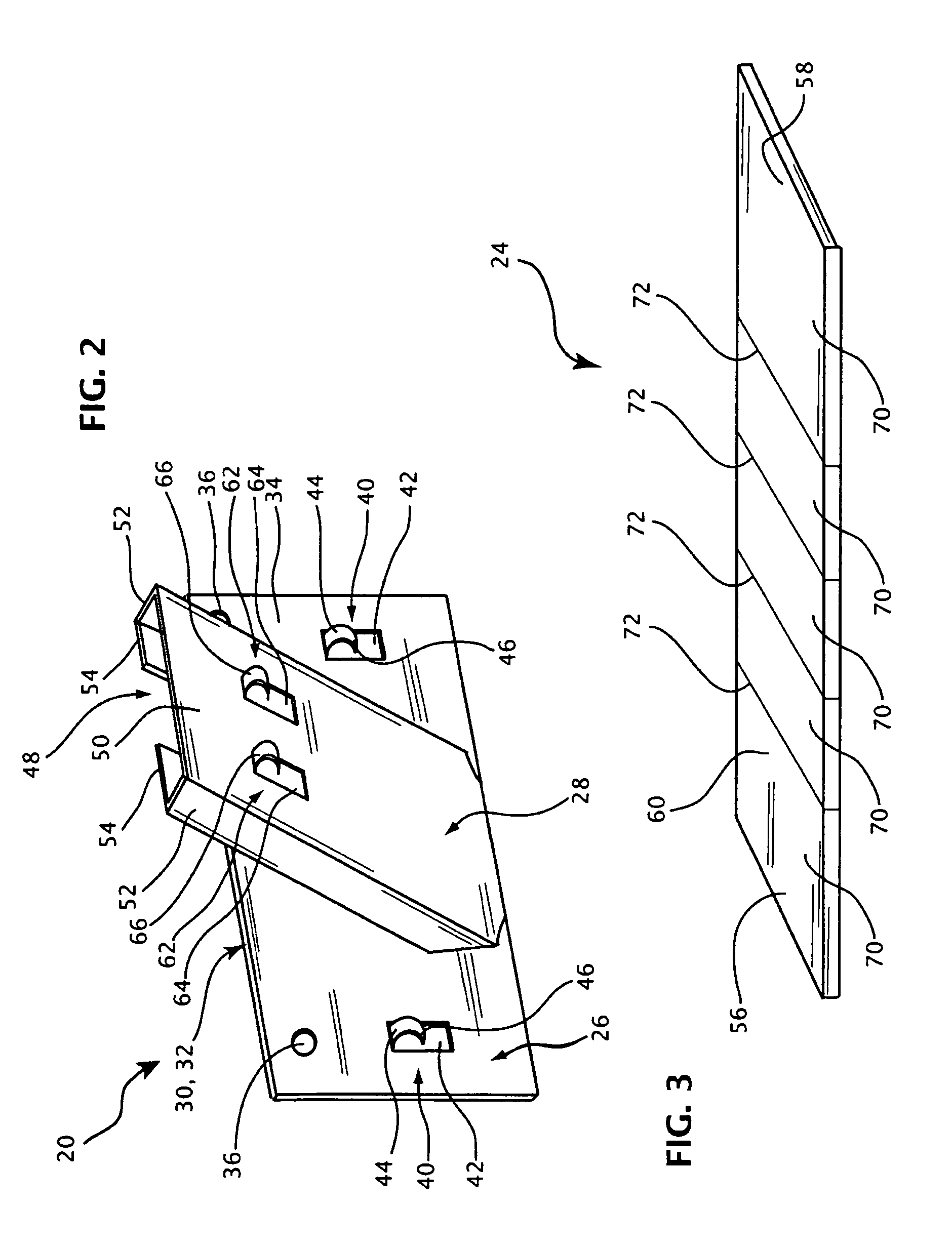
[0019]Referring to FIGS. 1 and 2, the installation bracket system 10 is comprised of one or more installation brackets 20 that are installed along the junction 14 for supporting the length of decorative crown molding 12. Each of the one or more installation brackets 20 consists of a pair of support members 22 and a backing member 24. ...


PUM


Abstract

An installation bracket system for use in combination with a length of crown molding for securing the crown molding adjacent to the junction of a wall surface and a ceiling surface, the installation bracket system including one or more installation brackets, each of the one or more installation brackets having first support member and a second support member, each of the support members having a mounting portion and an integrally formed supporting portion, the mounting portion having a base formed with apertures to receive fasteners therethrough for securement of the first support member and the second support member to the wall surface and ceiling surface, respectively, and a backing member extending between the first support member and the second support member, the backing member having a front surface, the crown molding being secured against the front surface of the backing member.

Description

FIELD OF THE INVENTION[0001]The present invention relates to an installation bracket for crown molding. The present invention further relates to an installation bracket system for facilitating the installation of crown molding along a junction between a wall surface and a ceiling surface.BACKGROUND OF THE INVENTION[0002]Crown molding is a decorative material commonly installed in commercial and residential buildings for aesthetic purposes. Crown molding has also been used for functional purposes, such as for concealing exposed pipes or wires when renovating an existing commercial or residential building. The installation of a length of crown molding along the junction of wall and ceiling surfaces requires a considerable amount of expertise and patience, especially when minute adjustments to the positioning of the crown molding are required to properly install the molding along the wall and ceiling surfaces.[0003]In commercial and residential buildings constructed with concrete wall ...

Claims


Application Information

Patent Timeline
Patent Type & Authority Patents(United States)
IPC IPC(8): E04B2/00
CPCE04F21/00E04F19/0436
Inventor DE RAUCOURT, JEAN-CLAUDE
Owner DE RAUCOURT JEAN CLAUDE
Why Eureka
Try Eureka