Variable displacement swash-plate compressor
a compressor and variable displacement technology, applied in the direction of machines/engines, pumps, positive displacement liquid engines, etc., can solve the problems of pressure leakage in the control pressure chamber, the hinge ball cannot be smoothly moved along the drive shaft axis, and the movable body cannot stably decrease the inclination angle of the swash plate, etc., to achieve sufficient controllability and minimize the effect of siz
- Summary
- Abstract
- Description
- Claims
- Application Information
AI Technical Summary
Benefits of technology
Problems solved by technology
Method used
Image

Examples
first embodiment
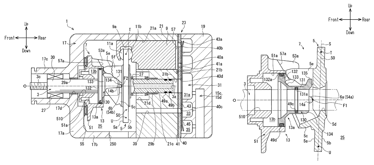
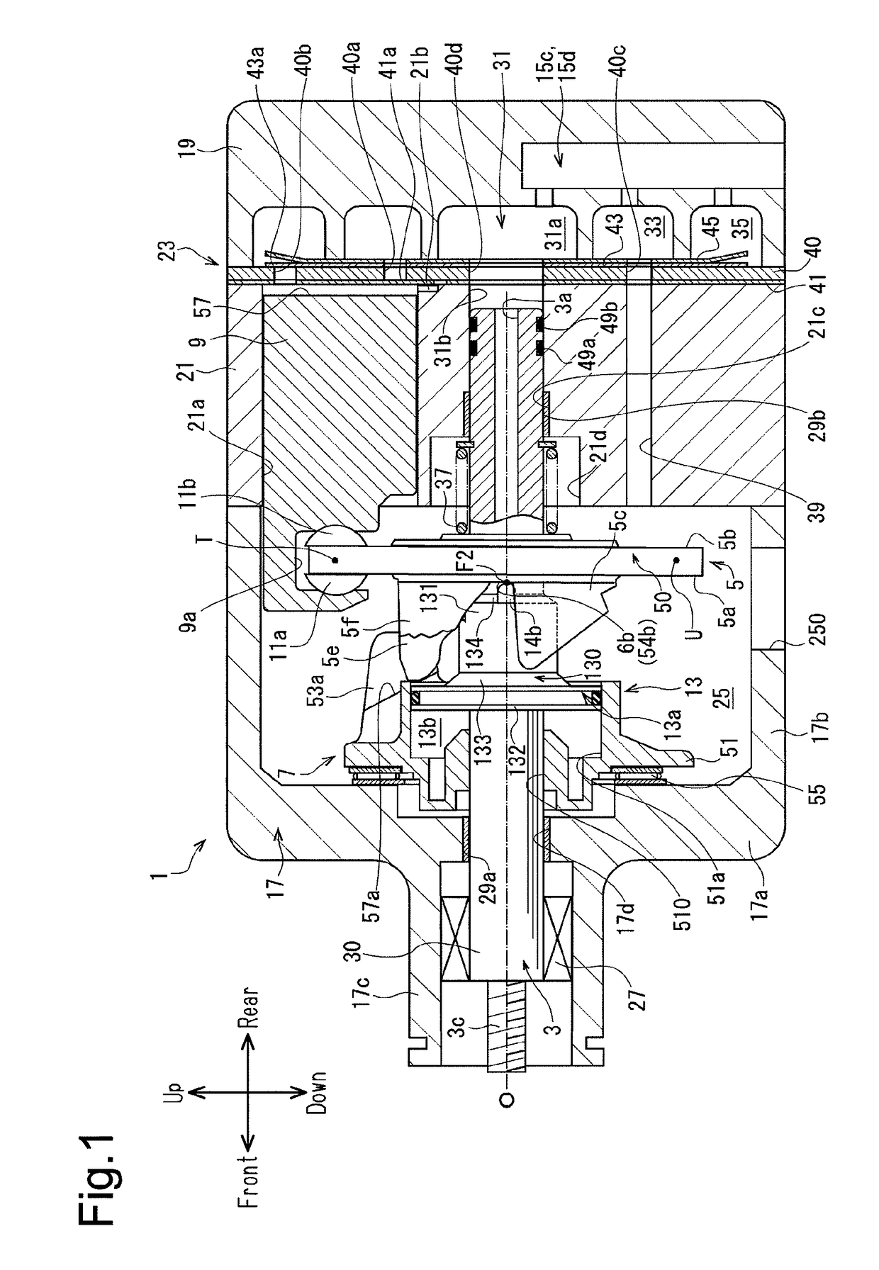
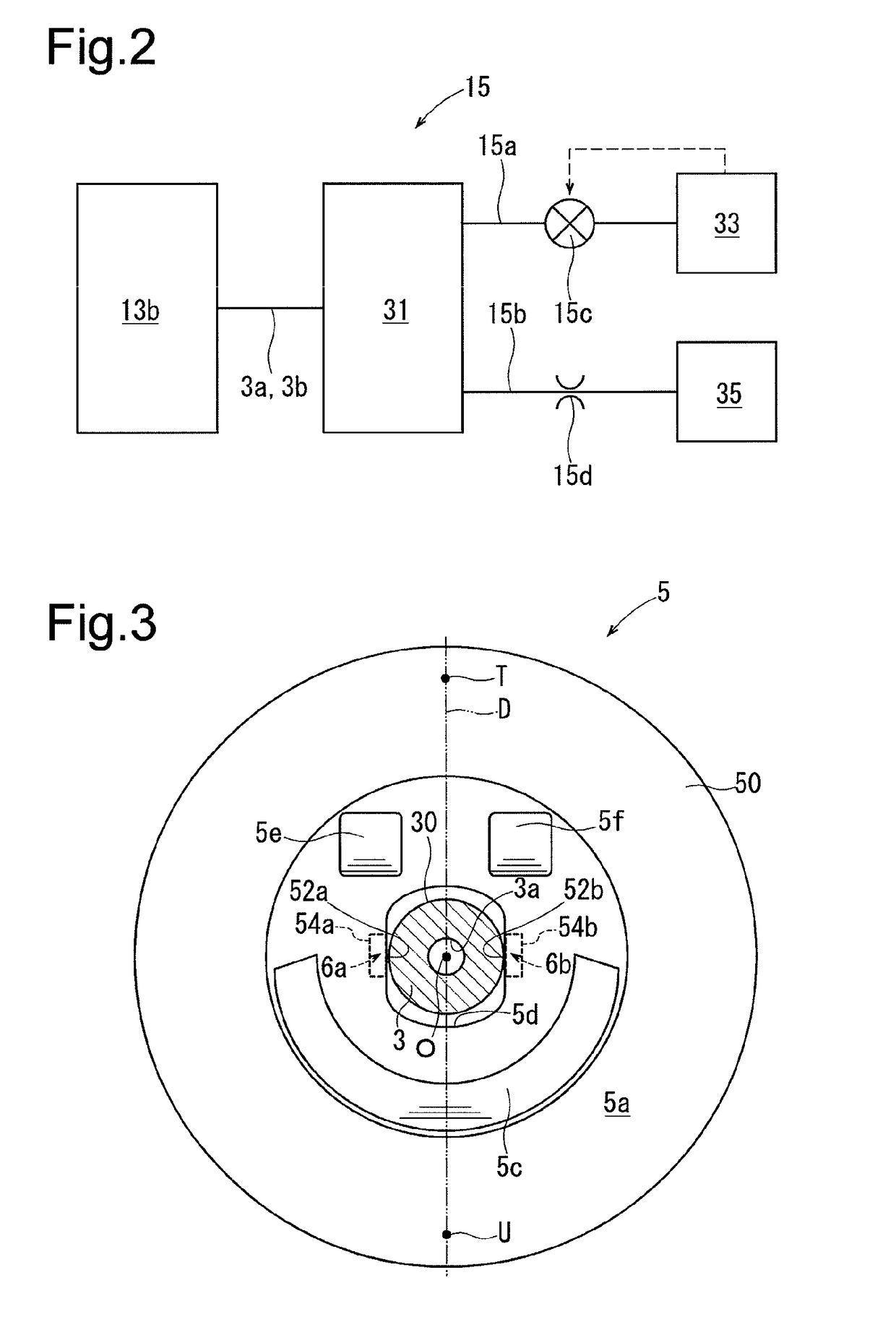
[0030]As shown in FIG. 1, the compressor according to the first embodiment includes a housing 1, a drive shaft 3, a swash plate 5, a link mechanism 7, pistons 9, pairs of shoes 11a, 11b, an actuator 13, and a control mechanism 15, which is illustrated in FIG. 2.
[0031]As shown in FIG. 1, the housing 1 has a front housing member 17 at a front position in the compressor, a rear housing member 19 at a rear position in the compressor, and a cylinder block 21 and a valve assembly plate 23, which are arranged between the front housing member 17 and the rear housing member 19.
[0032]The front housing member 17 includes a front wall 17a, which extends in the vertical direction of the compressor on the front side, and a circumferential wall 17b, which is integrated with the front wall 17a and extends rearward from the front of the compressor. The front housing member 17 has a substantially cylindrical cup shape with the front wall 17a and the circumferential wall 17b. Furthermore, the front wa...
second embodiment
[0095]In the compressor according to the second embodiment, the first and second receiving surfaces 54a, 54b of the compressor according to the first embodiment are replaced by a receiving surface 54c as shown in FIG. 10. The receiving surface 54c is also arranged on the front surface 5a of the swash plate main portion 50 and about the through hole 5d. The receiving surface 54c has a flat section 540 and first and second protrusions 6c, 6d. As shown in FIG. 13, the flat section 540 is a flat surface parallel with the swash plate reference plane S.
[0096]The first protrusion 6c extends along the drive shaft axis O and in a direction from the flat section 540 toward the movable body main portion 130. The distal end of the first protrusion 6c, that is, the part that faces the movable body main portion 130, has a cylindrical shape protruding toward the movable body 13a. The second protrusion 6d, which is shown in FIG. 10, has the same structure as the first protrusion surface 6c. The fir...
third embodiment
[0106]The compressor of the third embodiment has a receiving surface 54d as shown in FIG. 14. The receiving surface 54d is also arranged on the front surface 5a of the swash plate main portion 50 and about the through hole 5d. The receiving surface 54d has a mortar portion 541 and first and second protrusions 6e, 6f. As shown in FIG. 17, the mortar portion 541 has a decreasing diameter along the drive shaft axis O to conform to the acting surface 134 regardless of the inclination angle of the swash plate 5.
[0107]The first protrusion 6e extends in a direction from the mortar portion 541 toward the movable body main portion 130. The distal end of the first protrusion 6e has a cylindrical shape protruding toward the movable body 13a. The second protrusion 6f, which is shown in FIG. 14, has the same structure as the first protrusion 6e. The first and second protrusions 6e, 6f correspond to first and second receiving portions, respectively.
[0108]The first protrusion 6e and the second pro...
PUM
 Abstract
Description
Claims
Application Information