Supercharge Your Innovation With Domain-Expert AI Agents!

Thin-film magnetic head having magnetic layer with non-magnetic portion

a thin film, non-magnetic technology, applied in the direction of heads with metal sheet cores, instruments, data recording, etc., can solve the problem of negligible effect on adjacent tracks, and achieve the effect of suppressing the cause, not reducing the leakage field, and sufficient controllability of the width of the magnetic pol

Inactive Publication Date: 2010-10-19
TDK CORPARATION
View PDF6 Cites 0 Cited by
  • Summary
  • Abstract
  • Description
  • Claims
  • Application Information

AI Technical Summary

Benefits of technology

The design effectively reduces ATE while ensuring sufficient write field intensity and controllability of the magnetic pole width, even at increased skew angles, by limiting leakage fields and maintaining write field performance comparable to conventional heads.

Problems solved by technology

Therefore, even if the skew angle increases, a leakage field from the lower magnetic pole layer that can cause ATE is limited to such a degree that it has a negligibly small effect on adjacent tracks.

Method used


Image

  • Thin-film magnetic head having magnetic layer with non-magnetic portion
  • Thin-film magnetic head having magnetic layer with non-magnetic portion
  • Thin-film magnetic head having magnetic layer with non-magnetic portion

Examples


Embodiment Construction

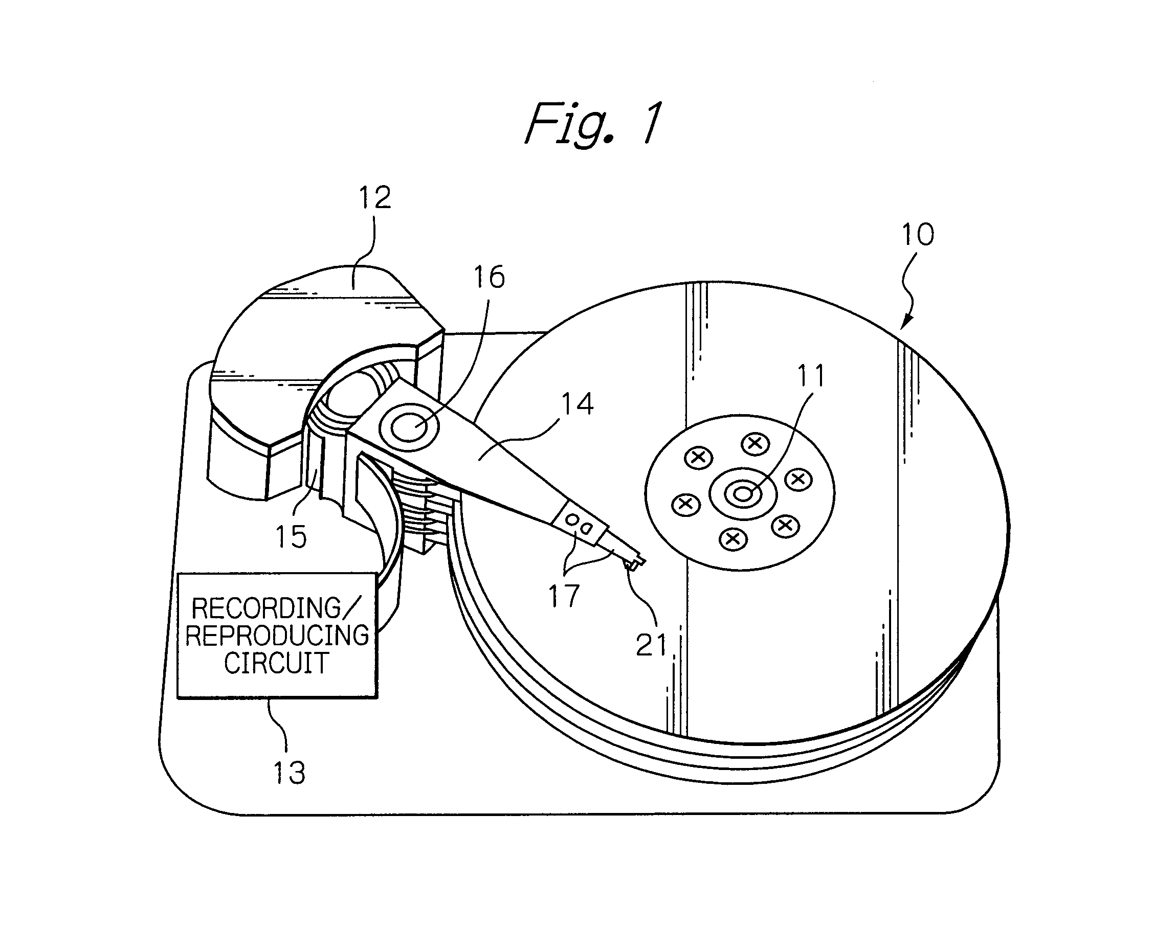
[0043]FIG. 1 shows a perspective view schematically illustrating a configuration of a main part of an embodiment of a magnetic disk drive apparatus according to the present invention.

[0044]In FIG. 1, reference numeral 10 denotes multiple magnetic disks that rotates about the spindle of a spindle motor 11, 12 denotes an assembly carriage device for positioning a thin-film magnetic head (slider) 21 above a track, and 13 denotes a recording / reproducing circuit for controlling read / write operations of the thin-film magnetic head.

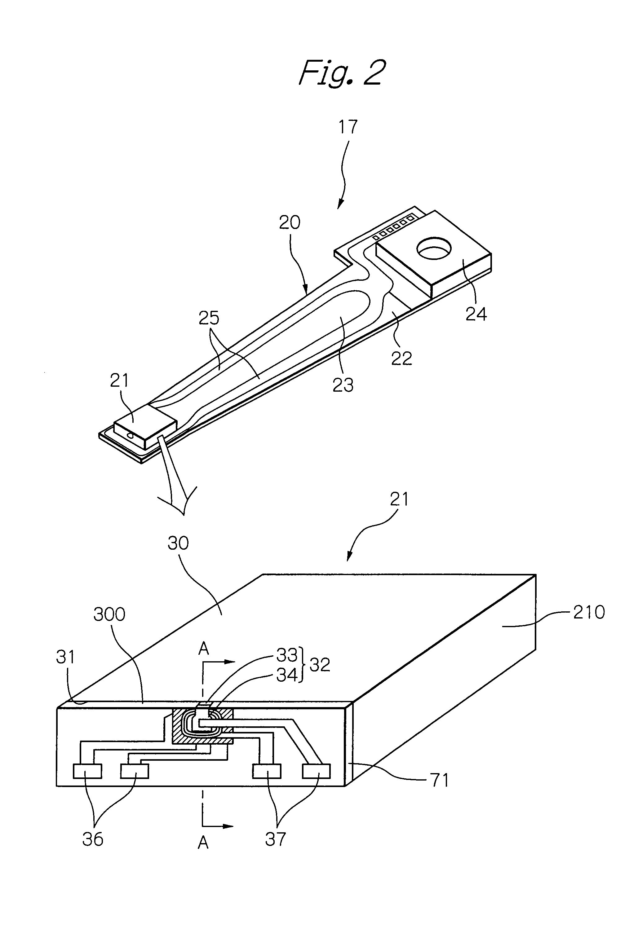
[0045]Provided in the assembly carriage device 12 are multiple drive arms 14. The drive arms 14 are capable of angular-pivoting about a pivot bearing axis 16 driven by a voice coil motor (VCM) 15 and are stacked along the axis 16. An HGA 17 is attached in the end of each drive arm 14. Provided in each HGA 17 is a thin-film magnetic head (slider) 21 in such a manner that it faces the surface of each magnetic disk 10. The numbers of magnetic disks 10, drive arms 1...


PUM

PropertyMeasurementUnit
thickness tLPaaaaaaaaaa
thicknessaaaaaaaaaa
saturation magnetic flux densityaaaaaaaaaa

Abstract

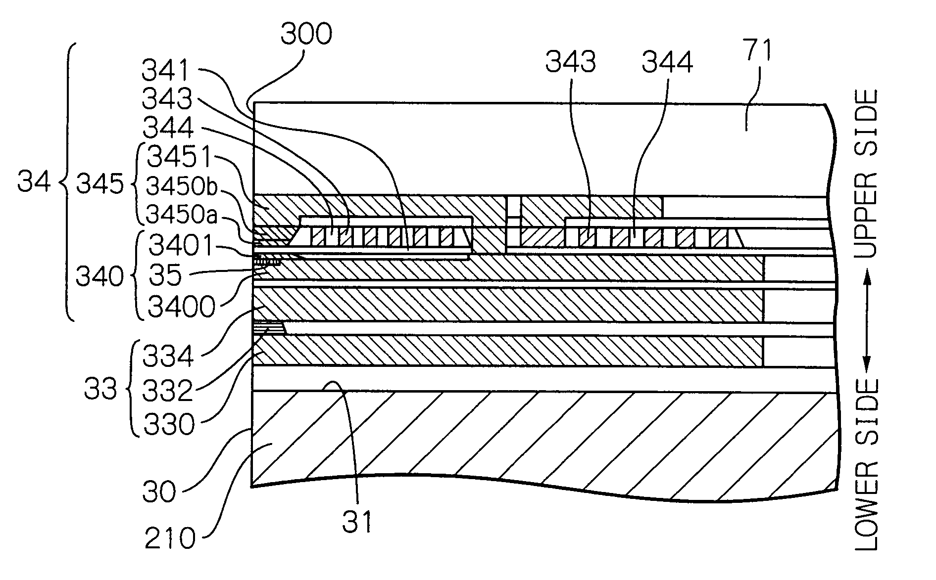
Provided is a thin-film magnetic head capable of suppressing ATE while ensuring sufficient controllability of the magnetic pole width and sufficient write field intensity. The head includes an electromagnetic coil element comprising: upper and lower magnetic layers; a write gap layer; and a write coil layer, the lower magnetic layer comprising: a lower yoke layer, a non-magnetic portion formed on an end portion on the ABS side of the lower yoke layer and extending to a head end surface on the ABS side; and a lower magnetic pole layer, an upper surface of the lower magnetic pole layer being in contact with the write gap layer, and an end surface in the head end surface of the lower magnetic pole layer having a shape whose width along a track width direction is defined by a predetermined magnetic pole width.

Description

PRIORITY CLAIM[0001]This application claims priority from Japanese patent application No. 2006-125282, filed on Apr. 28, 2006, which is incorporated herein by reference.BACKGROUND OF THE INVENTION[0002]1. Field of the Invention[0003]The present invention relates to a thin-film magnetic head for magnetic recording including an electromagnetic coil element having magnetic layers, a head gimbal assembly (HGA) including the thin-film magnetic head, and a magnetic disk drive apparatus including the HGA.[0004]2. Description of the Related Art[0005]With the increasing demand for small, and yet high-capacity magnetic disk drive apparatus in recent years, further improvements in recording density have become essential. Important factors for increasing recording density include a reduction in the width along the track-width direction of the magnetic pole of the electromagnetic coil element in thin-film magnetic heads and an improvement of the intensity of the write field generated from the ma...

Claims


Application Information

Patent Timeline
Patent Type & Authority Patents(United States)
IPC IPC(8): G11B5/127G11B5/147
CPCG11B5/1872G11B5/3116G11B5/314
Inventor HIRABAYASHI, HIRAKUANAGAWA, KENKICHI
Owner TDK CORPARATION
Features
  • R&D
  • Intellectual Property
  • Life Sciences
  • Materials
  • Tech Scout
  • Unparalleled Data Quality
  • Higher Quality Content
  • 60% Fewer Hallucinations
Learn More