Supercharge Your Innovation With Domain-Expert AI Agents!

Variable displacement swash plate type compressor

a compressor and variable displacement technology, applied in the direction of machines/engines, pump control, positive displacement liquid engines, etc., can solve the problems of large small compression capacity per rotation of the drive shaft, and increased compressor size, etc., to achieve the effect of sufficient controllability

Inactive Publication Date: 2016-08-04
TOYOTA IND CORP
View PDF4 Cites 1 Cited by
  • Summary
  • Abstract
  • Description
  • Claims
  • Application Information

AI Technical Summary

Benefits of technology

The present invention is a compressor that can achieve better control while being made smaller than possible.

Problems solved by technology

Therefore, a compression capacity per rotation of the drive shaft becomes small.
Therefore, the compression capacity per rotation of the drive shaft becomes large.
Therefore, the size of the compressor tends to be increased due to a large swash plate chamber.
Furthermore, in this compressor, it is inevitable that blow-by gas having a high pressure flows into the swash plate chamber.
Furthermore, in this compressor, when the outside air temperature drops, the refrigerant in the swash plate chamber is likely to condense and liquid accumulation occurs in the swash plate chamber.
For these reasons, in this compressor, it is difficult to change the inclination angle suitably.
Therefore, the stroke of the pistons decreases and the discharge capacity becomes small.
Therefore, the stroke of the pistons increases and the discharge capacity becomes large.

Method used


Image

  • Variable displacement swash plate type compressor
  • Variable displacement swash plate type compressor
  • Variable displacement swash plate type compressor

Examples


embodiment 1

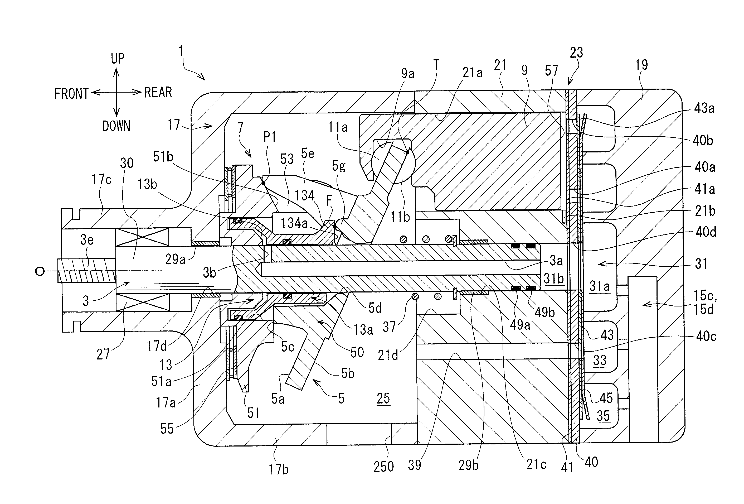
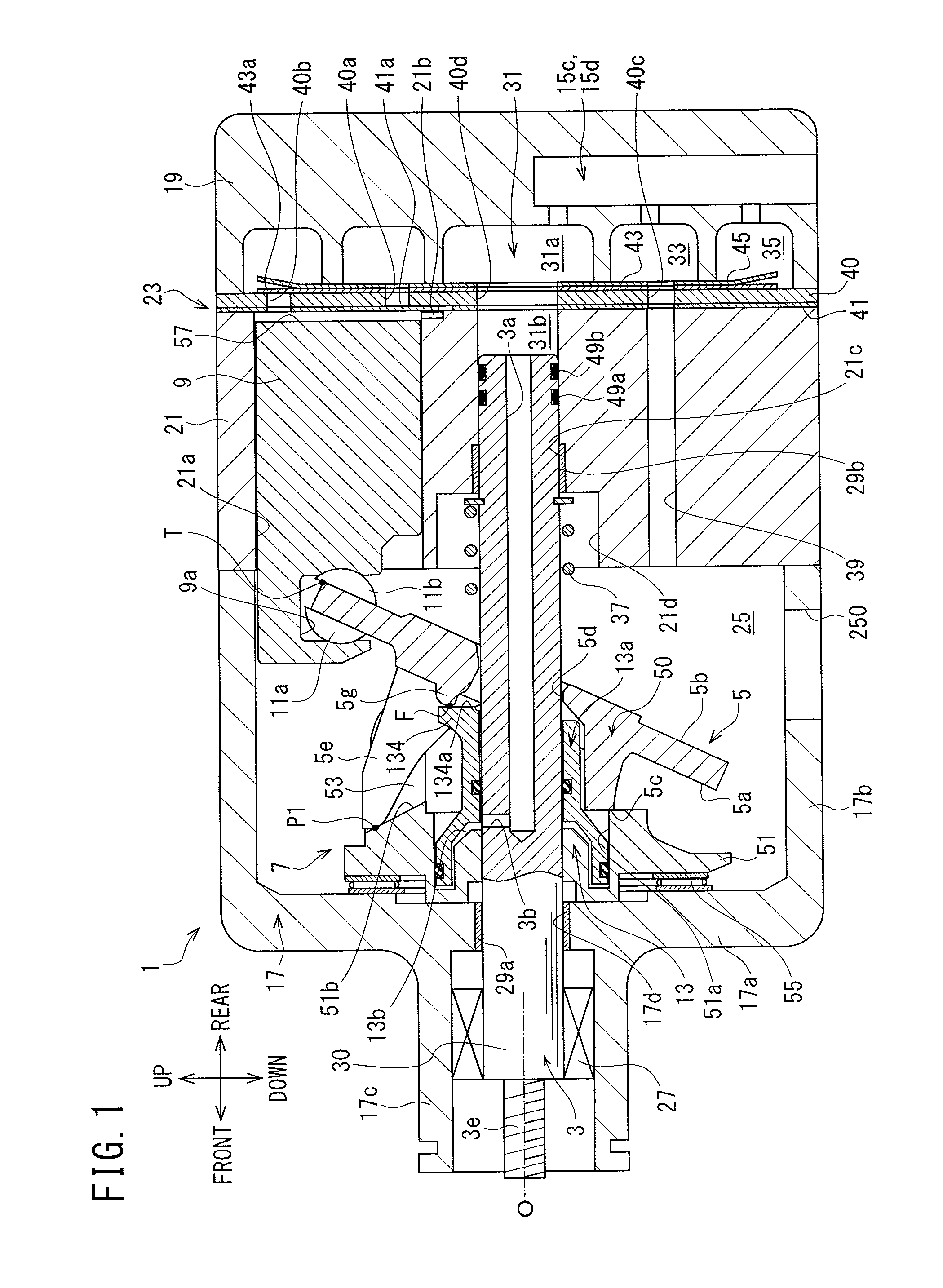
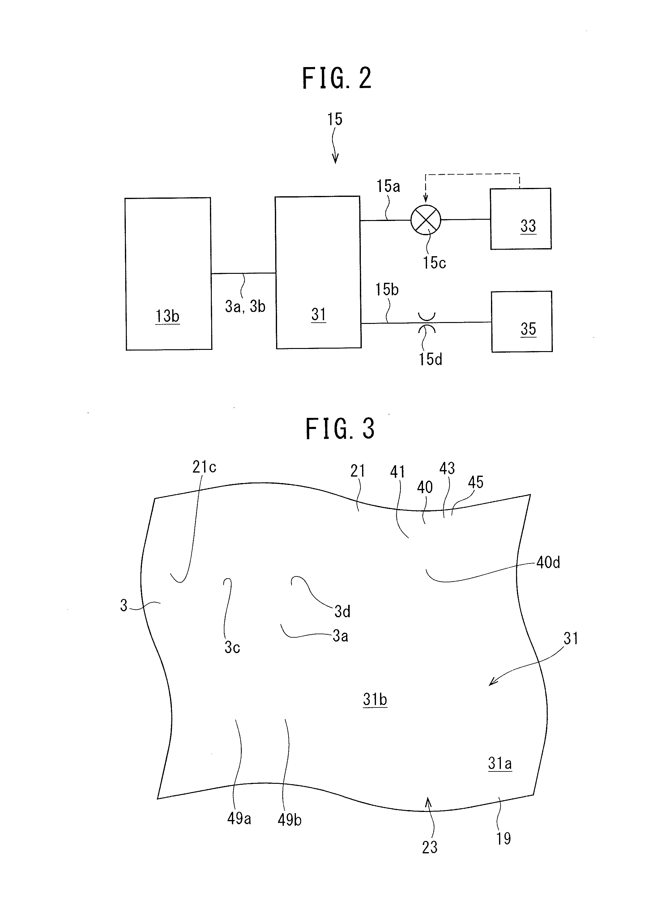
[0053]As shown in FIG. 1, the compressor of Embodiment 1 includes a housing 1, a drive shaft 3, a swash plate 5, a link mechanism 7, a plurality of pistons 9, a plurality of pairs of shoes 11a and 11b, an actuator 13, and a control mechanism 15, which is shown in FIG. 2. In FIG. 1, the illustration of the swash plate 5 is partially simplified for ease of explanation. The same applies to FIGS. 7 and 10, which will be described later.

[0054]As shown in FIG. 1, the housing 1 has a front housing 17 that is located at a front side in the compressor, a rear housing 19 that is located at a rear side in the compressor, a cylinder block 21 that is located between the front housing 17 and the rear housing 19, and a valve unit 23.

[0055]The front housing 17 has a front wall 17a that extends in the up-down direction of the compressor at the front side, and a circumferential wall 17b that is integrated with the front wall 17a and extends rearward from the front side of the compressor. By the front...

embodiment 2

[0117]As shown in FIG. 11, in a compressor of Embodiment 2, the swash plate 5 has the swash plate main body 50, the swash plate arms 5e and 5f and a contact member 59. The contact member 59 also corresponds to the acted portion in the present invention.

[0118]The contact member 59 is formed to be a separate body from the swash plate main body 50. The contact member 59 is attached to the front surface 5a of the swash plate main body 50 at a position between the swash plate arms 5e and 5f, and located eccentrically toward the top-dead-center corresponding portion T of the swash plate 5 from the driving axis O.

[0119]A protrusion 59a that protrudes frontward is formed at the contact member 59. The protrusion 59a is formed into a substantially hemispherical shape. The protrusion 59a comes into point-contact with the acting surface 134a of the acting portion 134 at the operative position F. In this manner, in this compressor, via the acting surface 134a and the protrusion 59a, the acting p...


PUM


Abstract

A variable displacement swash plate type compressor includes an actuator. The actuator has a lug member, a movable body that is rotatable integrally with a swash plate and is capable of changing an inclination angle of the swash plate by moving in the direction of an driving axis, and a control pressure chamber that is defined by the lug member and the movable body and moves the movable body by changing its internal pressure by a control mechanism. An acting portion that is capable of pressing the swash plate by the pressure in the control pressure chamber is formed at the movable body, and an acted portion that abuts on and is pressed by the acting portion is formed at the swash plate

Description

TECHNICAL FIELD[0001]The present invention relates to a variable displacement swash plate type compressor.BACKGROUND ART[0002]Patent Literature 1 discloses a conventional variable displacement swash plate type compressor (hereinafter referred to as a compressor). This compressor comprises a housing, a drive shaft, a swash plate, a link mechanism, a plurality of pistons, a conversion mechanism, and a capacity control mechanism.[0003]In the housing, a suction chamber, a discharge chamber, a swash plate chamber and a plurality of cylinder bores are formed. The drive shaft is rotatably supported by the housing. The swash plate is rotatable in the swash plate chamber by rotation of the drive shaft. The link mechanism is provided between the drive shaft and the swash plate and permits change of an inclination angle of the swash plate with respect to a direction perpendicular to a driving axis of the drive shaft. The link mechanism has a lug member and a transmission member. The lug member...

Claims


Application Information

Patent Timeline
Patent Type & Authority Applications(United States)
IPC IPC(8): F04B27/10F04B27/08F04B49/22F04B27/18
CPCF04B27/1063F04B27/1072F04B27/18F04B49/225F04B27/1009F04B27/1045F04B27/0878
Inventor YAMAMOTO, SHINYAYAMAZAKI, YUSUKESUZUKI, TAKAHIROHONDA, KAZUNARIOTA, MASAKINAKAIMA, HIROYUKI
Owner TOYOTA IND CORP
Features
  • R&D
  • Intellectual Property
  • Life Sciences
  • Materials
  • Tech Scout
  • Unparalleled Data Quality
  • Higher Quality Content
  • 60% Fewer Hallucinations
Learn More