Head-mounted optical coherence tomography

a head-mounted optical coherence tomography and optical coherence technology, applied in the field of non-invasive imaging and analysis techniques, can solve the problems of fiber based systems using fiber stretchers with speed limitations, size and polarization issues, and the risk of infection associated with pain and discomfor

Active Publication Date: 2018-02-13
COMPACT IMAGING
View PDF2 Cites 13 Cited by
  • Summary
  • Abstract
  • Description
  • Claims
  • Application Information

AI Technical Summary

Problems solved by technology

In the case of analyzing living entities, such as human tissue, undesirable side effects of invasive analysis include the risk of infection along with pain and discomfort associated with the invasive process.
Electro-mechanical voice coil actuators can have considerable scanning range, however, there are problems with maintaining stability or pointing accuracy of a reference mirror.
Fiber based systems using fiber stretchers have speed limitations and have size and polarization issues.
Rotating diffraction gratings can run at higher speeds, but are alignment sensitive and have size issues.
Piezo devices can achieve high speed scanning and can have high pointing accuracy, however to achieve a large scanning range requires expensive control systems and such systems have limited speed.
The technique described in these publications uses multiple reference signals with increasing scan range and correspondingly increasing frequency interference signals.
Currently available OCT systems are bulky, weighty, complex and high cost.
Currently available OCT systems have complex and bulky alignment and scanning sub-systems that result in physically large and costly systems.
Currently available OCT systems that require fixation at locations other than the location being analyzed by the OCT beam also require a complex fixation mechanism.
People who are at risk of eye damage from these conditions need frequent monitoring because occurrence of an adverse situation (for example the growth of weak and leaky blood vessels), if not addressed in a timely manner, can cause irreversible damage to the retina leading inexorably to loss of vision.
Many of these visits are wasteful if nothing has changed and in the case of a change, significant irreversible damage can occur within a month.

Method used


Image

  • Head-mounted optical coherence tomography
  • Head-mounted optical coherence tomography
  • Head-mounted optical coherence tomography

Examples


Embodiment Construction

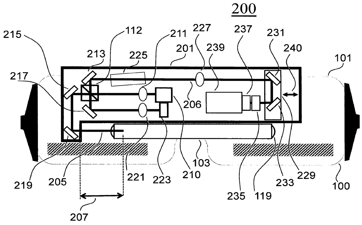
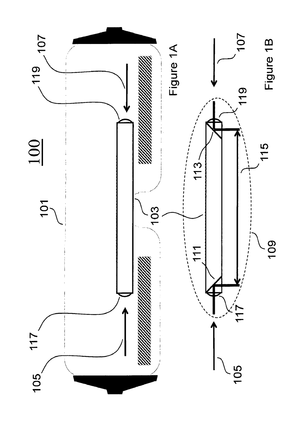
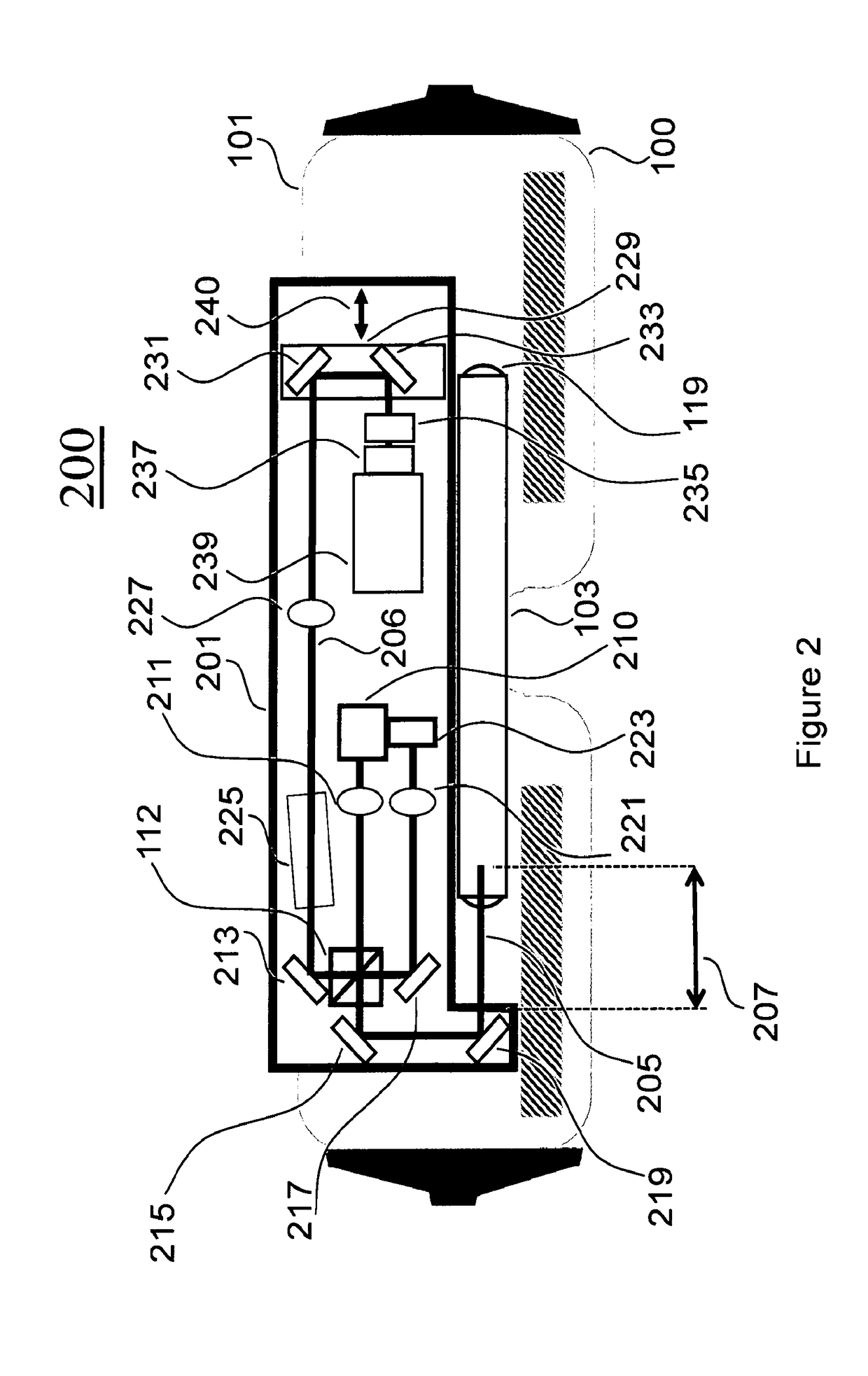
[0036]The invention taught herein includes a device and method of non-invasively measuring aspects of a component of an eye. Such components include, but are not limited to, the retina of an eye. Such aspects include, but are not limited to: the thickness of the retina at a particular location; the thickness of the retina at a set of locations; a depth scan of the retina at one or more locations; a two dimensional scan of a region of the retina where one dimension is depth.

[0037]In the preferred embodiment, an OCT photonic module directs a light beam, referred to as a probe beam, into the eye and captures at least a portion of the light that is scattered back towards the OCT photonic module. This back-scattered light is combined with reference light to form one or more interference signals that can be processed to a yield depth scan of the retina.

[0038]In the preferred embodiment a frame is configured to fit a particular Subject (or set of subjects) whose eye is the target eye to be...


PUM


Abstract

The invention provides a system and method for obtaining ophthalmic measurements whereby the inventive device is configured to be head mountable, automatically axially length aligned with a selected target, and laterally aligned so that light from an OCT source enters through the pupil of the eye under test. The frame of the head mountable OCT is customizable, capable of analyzing both the left and right eye of a subject. The inventive device can be operated by the person undergoing test. Embodiments include mechanisms for eye fixation, lateral, angular and depth scanning of target regions. A variety of embodiments are taught, including the scanning of both eyes of a subject at substantially the same time, and a configuration of a photonic module coupleable with a plurality of frames. Embodiments include a variety of OCT sources, such as MRO, swept source, time domain, and spectral domain.

Description

CROSS REFERENCES TO RELATED PATENTS OR APPLICATIONS[0001]This patent application, docket number CI130701PT, is related to U.S. Pat. No. 7,526,329 titled “Multiple Reference Non-invasive Analysis System” and U.S. Pat. No. 7,751,862 titled “Frequency Resolved Imaging System”, the contents of both of which are incorporated herein as if fully set forth herein. This patent application is also related to the following three patent applications, all of which were filed on Nov. 3, 2012: PCT patent application number PCT / US2012 / 063471 titled “Improved Correlation of Concurrent Non-invasively Acquired Signals”; patent application Ser. No. 13,668,261 titled “A Field of Light based Device”; and patent application Ser. No. 13,668,258 titled “Non-invasive Optical Monitoring”; the contents of all of which are incorporated herein as if fully set forth herein.FIELD OF THE INVENTION[0002]The invention described and illustrated in this application relates to non-invasive imaging and analysis technique...

Claims


Application Information

Patent Timeline
Patent Type & Authority Patents(United States)
IPC IPC(8): A61B3/10G02B27/00A61B3/14A61B3/02A61B3/00
CPCA61B3/102A61B3/0025G02B27/0068A61B3/1005A61B3/0091
Inventor HOGAN, JOSHUA NOEL
Owner COMPACT IMAGING
Why Eureka
Try Eureka