Methods, systems and computer program products for using time domain reflectometry signatures to monitor network communication lines

a technology of time domain reflectometry and network communication lines, applied in the field of network patching systems, can solve the problems of not being able to provide that employee, taking a significant amount of time for a technician to manually trace a particular patch cord, and manual tracing may not be completely accura

Inactive Publication Date: 2009-07-09
COMMSCOPE INC
View PDF17 Cites 169 Cited by
  • Summary
  • Abstract
  • Description
  • Claims
  • Application Information

AI Technical Summary

Benefits of technology

[0013]In some embodiments, a current TDR signature can be used to identify a connection path for a communication line. For example, a TDR signature can be used to identify where a communication line is connected via one or more patch cords on a patch panel, other devices, etc.

Problems solved by technology

When an employee changes office locations, it may not be desirable to provide that employee with new exchange numbers.
It may take a significant amount of time for a technician to manually trace a particular patch cord, particularly within a collection of other patch cords.
Furthermore, manual tracing may not be completely accurate and technicians may accidentally go from one patch cord to another during a manual trace.
Such errors may result in misconnected telecommunication lines which must be later identified and corrected.
Also, it may be difficult to identify the correct port to which a particular patch cord end should be connected or disconnected.
Thus, ensuring that the proper connections are made can be very time-consuming, and the process is prone to errors in both the making of connections and in keeping records of the connections.
In addition, changes in patch panel connections can be difficult to detect.
A communication line fault may include anything associated with a communication line that does not meet transmission guidelines or tolerances.

Method used


Image

  • Methods, systems and computer program products for using time domain reflectometry signatures to monitor network communication lines
  • Methods, systems and computer program products for using time domain reflectometry signatures to monitor network communication lines
  • Methods, systems and computer program products for using time domain reflectometry signatures to monitor network communication lines

Examples


Embodiment Construction

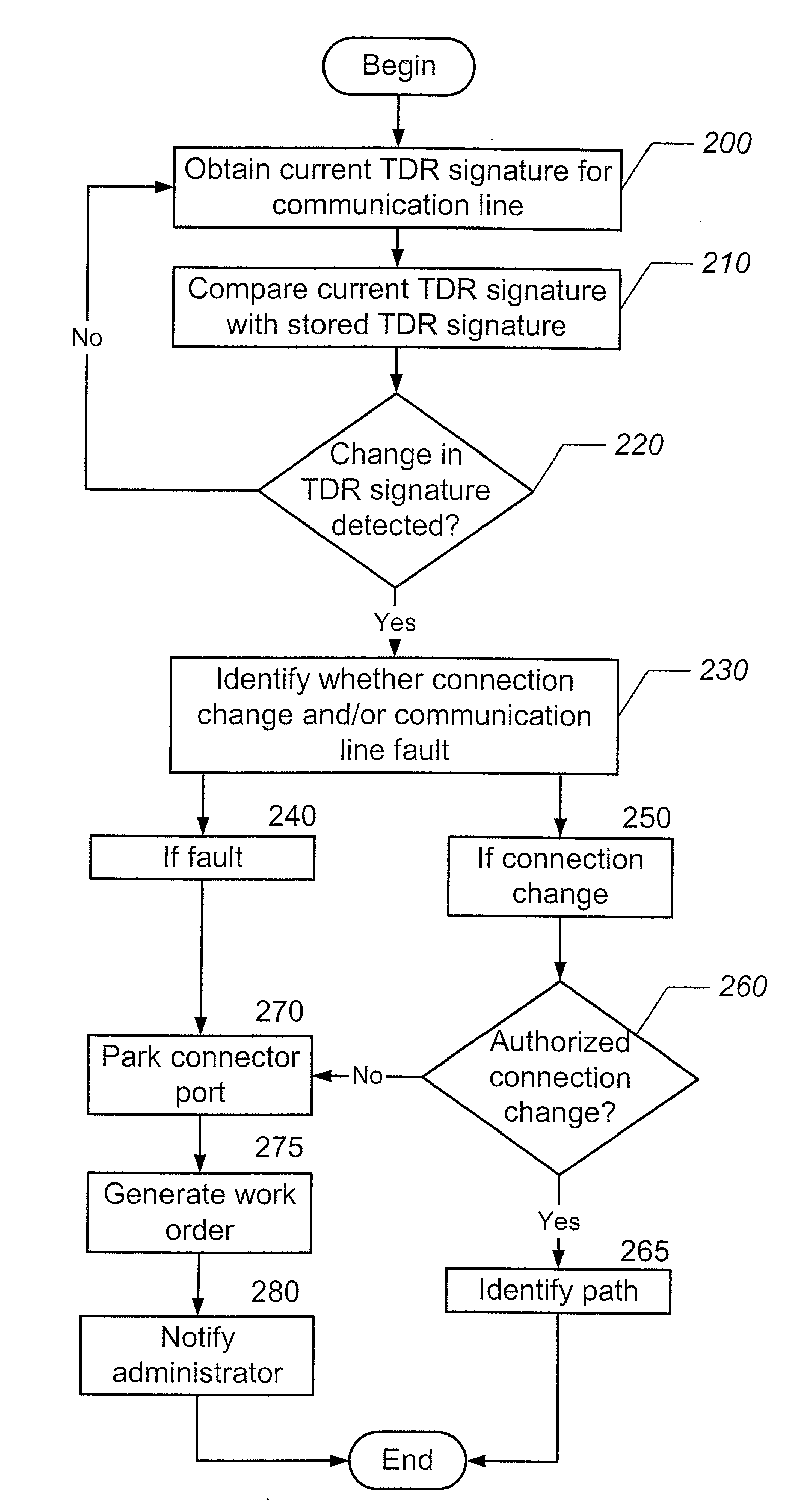
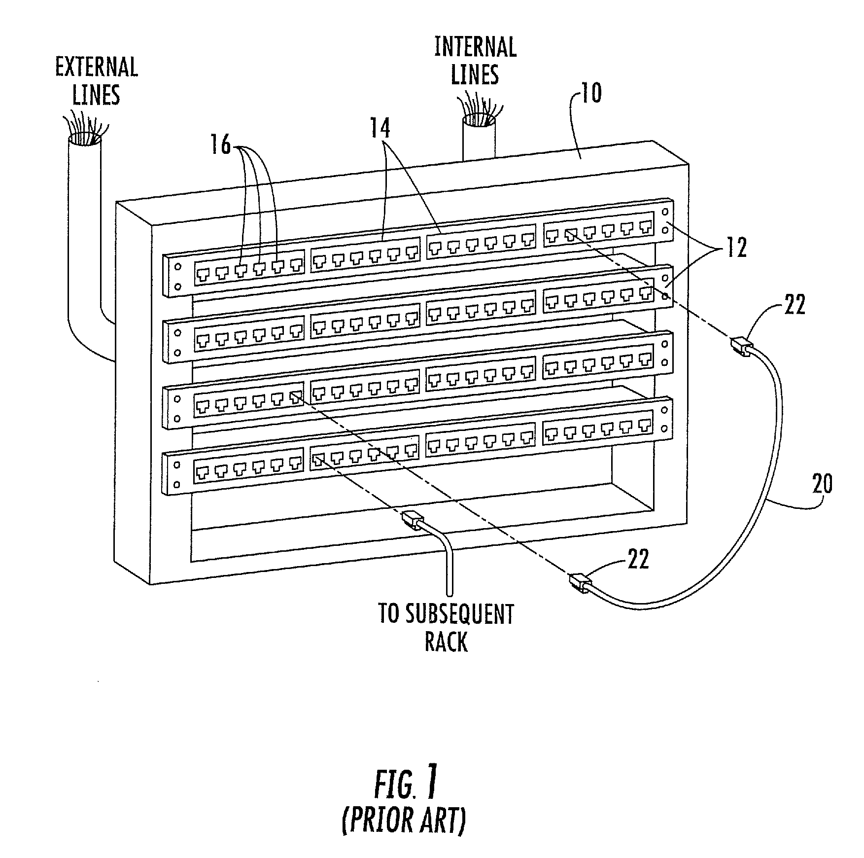
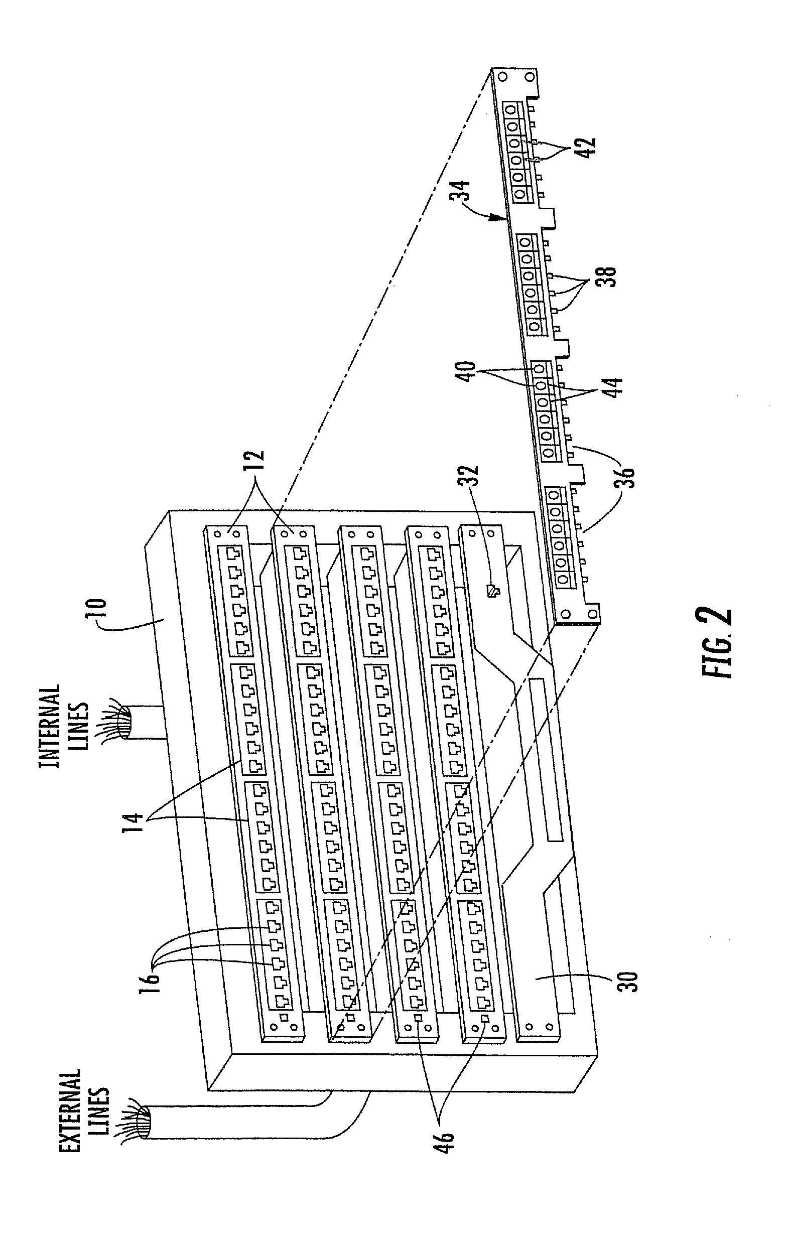
[0018]The present invention now will be described more fully hereinafter with reference to the accompanying drawings, in which illustrated embodiments of the invention are shown. This invention may, however, be embodied in many different forms and should not be construed as limited to the embodiments set forth herein. Rather, these embodiments are provided so that this disclosure will be thorough and complete, and will fully convey the scope of the invention to those skilled in the art. Like numbers refer to like elements throughout.

[0019]As used herein, the singular forms “a,”“an,” and “the” are intended to include the plural forms as well, unless expressly stated otherwise. It will be further understood that the terms “includes,”“comprises,”“including,” and / or “comprising,” when used in this specification, specify the presence of stated features, integers, steps, operations, elements, and / or components, but do not preclude the presence or addition of one or more other features, in...


PUM


Abstract

Methods, systems and computer program products for uniquely identifying communication lines in a network via time domain reflectometry (TDR) signatures are provided. A pulsed signal is sent into a communication line through a patch panel connector port and a reflection of the pulsed signal through the patch panel connector port is received to obtain a TDR signature for each communication line. The pulsed signal is sent and received by a controller operatively associated with the patch panel and / or by a network switch in communication with the patch panel. Connection changes and / or communication line faults at a network patch panel are detected by comparing current and stored TDR signatures.

Description

FIELD OF THE INVENTION[0001]The present invention relates generally to networks and, more particularly, to network patching systems.BACKGROUND OF THE INVENTION[0002]Many businesses, government agencies, education establishments, and other organizations have dedicated networks that enable computers, telephones, facsimile machines and the like to communicate with each other, and to communicate with devices in remote locations via a communications service provider. Conventionally, a dedicated network is hard wired using communication lines that contain conductive wires. In such hard wired systems, dedicated wires are coupled to individual service ports throughout a building, for example. The wires from the dedicated service ports conventionally extend throughout a building and into one or more closets. The communication lines from the interface hub of a main frame computer, network server or the like and the communication lines from external communication service providers may also ter...

Claims


Application Information

Patent Timeline
Patent Type & Authority Applications(United States)
IPC IPC(8): H04L12/28
CPCH04Q1/136G01R31/11H04L43/50H04Q1/14H04L63/1441
Inventor MACAULEY, DANIEL WARREN
Owner COMMSCOPE INC
Why Eureka
Try Eureka