
Method and system for autonomous vehicles

a technology for autonomous vehicles and vehicles, applied in the field of methods and systems for autonomous vehicles, can solve the problems of ineffectiveness, inability to accurately measure the distance between the camera and the vehicle, etc., and achieve the effect of cost and expense, convenient self-driving and steering mechanisms, and a lot of robustness

Active Publication Date: 2018-02-13
KOVARIK JOSEPH E +1
View PDF103 Cites 20 Cited by
  • Summary
  • Abstract
  • Description
  • Claims
  • Application Information

AI Technical Summary

Benefits of technology

The invention provides a way to get important information about the road and how well the vehicle is positioned relative to the center line of the desired path. This is done by using video sensing technology that works well in the dark and in poor visibility. This can help avoid obstacles and make proper turns.

Problems solved by technology

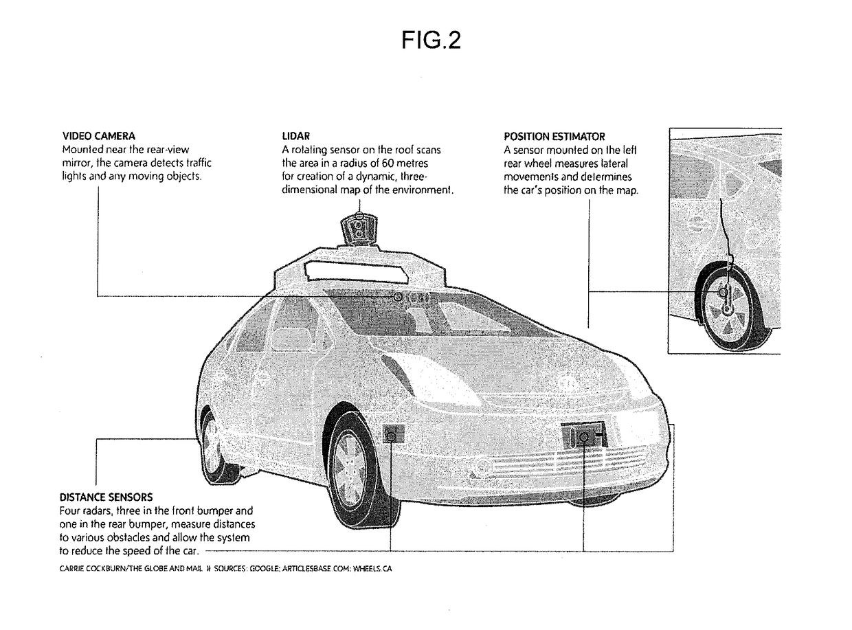
While radar sensing is possible, along with sonar or sound sensing, one is limited in correctly reading and interpreting radar or sonar echoes to insure obstacles are avoided and turns are made properly.
While “vision systems” may be employed to “read’ the paving markings on the existing roads—e.g. seeing yellow and white lines, etc.—adverse weather conditions can often obscure the same and make such camera sensors impractical or ineffective.

Method used


Image

  • Method and system for autonomous vehicles
  • Method and system for autonomous vehicles
  • Method and system for autonomous vehicles

Examples


Embodiment Construction

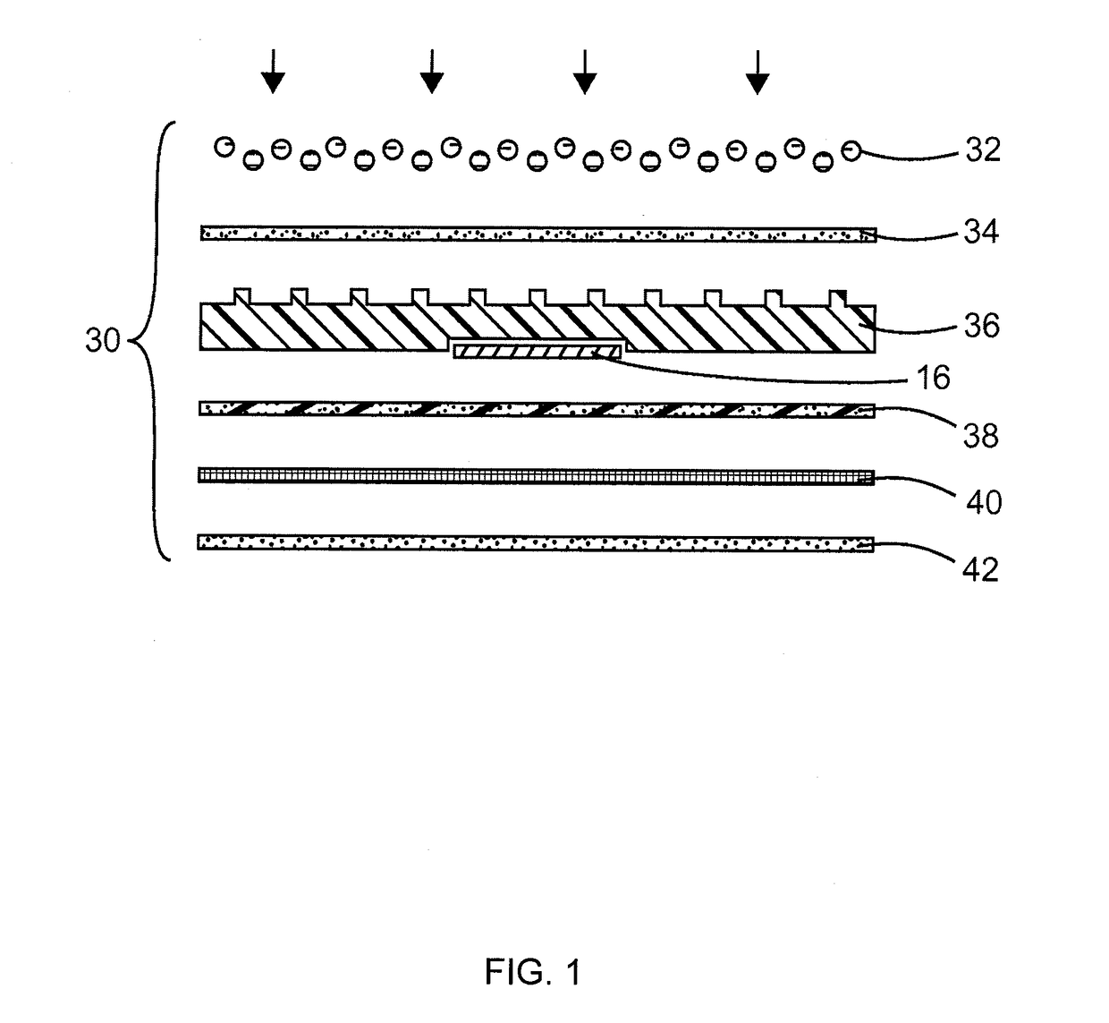
[0094]As described above and as illustrated in the figures, a first layer is a layer of glass beads. The glass beads are adhered to a textured rubber base 36 by a layer of adhesive. Inside the textured rubber base 36 there is a recess for receiving an RFID tag. The RFID tag is then held in place by a fiberglass netting and a layer of adhesive. The fiberglass netting also provides strength to the pavement marking material. Lastly, there is a layer of adhesive for adhering the pavement marking material to a road. Alternatively, the layer of glass beads and layer of adhesive may be substituted with Diamond Grade™ High Intensity Prismatic Sheeting, Series 3930, commercially available from 3M Company based in St. Paul.

[0095]In certain embodiments, a raised pavement marking material is employed that includes a top surface and a bottom surface opposite the top surface, two opposing angled side surfaces adjacent the top surface and bottom surface, with such surfaces being suitable for a mag...


PUM


Abstract

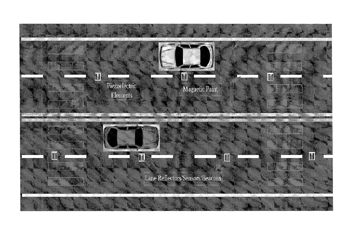
A method and system for facilitating cost effective, reliable, system redundant, self-driving vehicles involves the employment of specialized lane marking components that permit unprecedented sensor feedback, and in particular, a system and method that enables accurate lane marking recognition despite adverse weather conditions, which presently pose problems experienced by self-driving systems that rely upon vision based camera systems.

Description

RELATED APPLICATION[0001]This application seeks priority from U.S. Provisional Patent Application No. 62 / 078,539, filed on Nov. 12, 2014, and U.S. Provisional Patent Application No. 62 / 163,163, filed on May 18, 2015. The entire disclosure of the prior applications is considered to be part of the disclosure of the accompanying application and is hereby incorporated by reference.FIELD OF THE INVENTION[0002]A method and system for facilitating cost effective, reliable, system redundant, self-driving vehicles involves the employment of specialized lane marking components that permit unprecedented sensor feedback, and in particular, a system and method that enables accurate lane marking recognition despite adverse weather conditions, which presently pose problems experienced by self-driving systems that rely upon vision based camera systems.BACKGROUND OF THE INVENTION[0003]Worldwide, over a million people die on roads every year. More than 40% of fatal crashes in the U.S. involve alcohol...

Claims


Application Information

Patent Timeline
Patent Type & Authority Patents(United States)
IPC IPC(8): G06K7/10E01C9/00E01C11/00E01F9/30E01F9/576G05D1/02
CPCG06K7/10376E01F9/30E01F9/578G05D2201/0213G05D1/0259G05D1/0261Y02T10/70Y02T10/7072Y02T90/12G01S13/74G01S13/931G01S2013/9329G01S13/878G01S5/0205G05D1/243
Inventor KOVARIK, JOSEPH E.KOVARIK, JAMES J.
Owner KOVARIK JOSEPH E
Learn More