
Three-dimensional printing apparatus

a three-dimensional printing and printing machine technology, applied in metal-working machines, manufacturing tools, additive manufacturing, etc., can solve the problem of the total amount of optical energy applied to the area where the cross-sectional images are applied, and achieve the effect of reliable and reducing or eliminating the variations in the degree of curing of the photo-curable resin

Inactive Publication Date: 2018-03-13
ROLAND DG CORP
View PDF6 Cites 4 Cited by
  • Summary
  • Abstract
  • Description
  • Claims
  • Application Information

AI Technical Summary

Benefits of technology

[0011]Accordingly, preferred embodiments of the present invention provide a three-dimensional printing apparatus that prints a three-dimensional object while reducing or eliminating variations in a degree of curing of photo-curable resin without adjusting total amounts of optical energy to be applied from projectors.
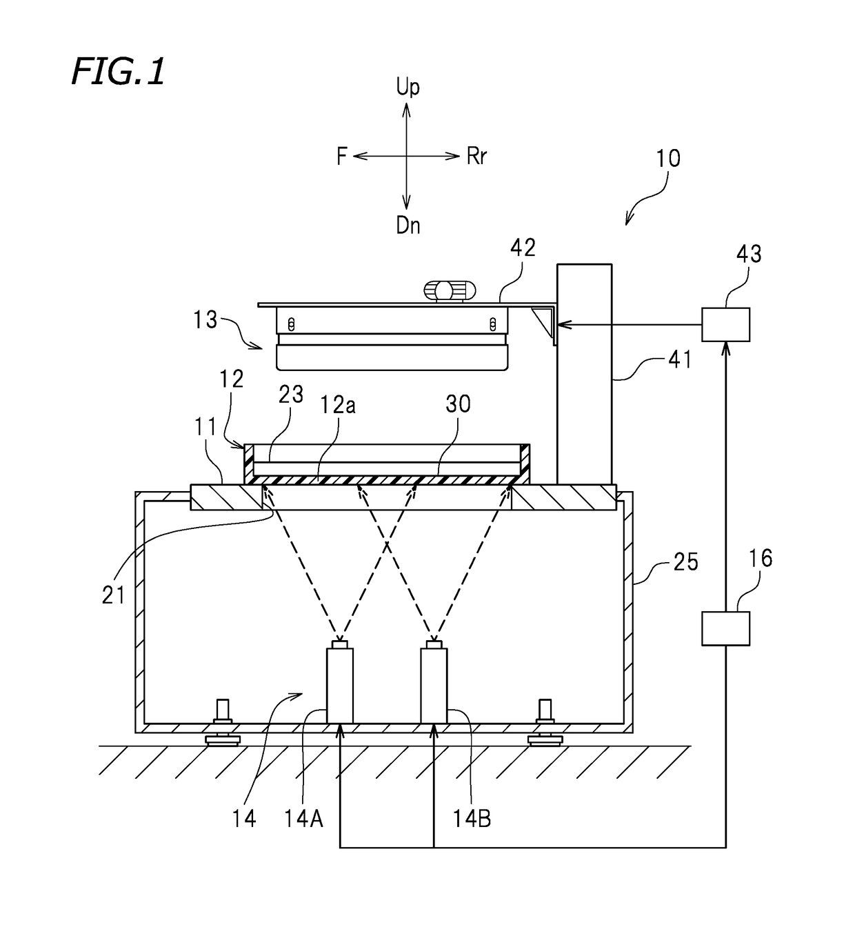
[0013]The projector of the three-dimensional printing apparatus according to this preferred embodiment of the present invention includes the first projector and the second projector. This enables the projector to project the cross-sectional image, which is larger in size, onto the image projecting surface. The first projecting operation involves simultaneously projecting the first cross-sectional sub-image and the second cross-sectional sub-image from the first projector onto the first area and the second area, respectively and the second cross-sectional sub-image and the third cross-sectional sub-image from the second projector onto the second area and the third area, respectively. This leaves no gap between a set of the first and second cross-sectional sub-images projected from the first projector and a set of the second and third cross-sectional sub-images projected from the second projector, thus enabling reliable curing of the photo-curable resin across an entirety of the first to third cross-sectional sub-images. During the first projecting operation, the first projector and the second projector each project the second cross-sectional sub-image onto the second area, which means that the number of cross-sectional sub-images to be projected onto the second area is larger than the number of cross-sectional sub-images to be projected onto each of the first area and the third area. In this preferred embodiment, however, the controller further performs the second projecting operation. Specifically, the second projecting operation involves simultaneously projecting the first cross-sectional sub-image from the first projector onto the first area and the third cross-sectional sub-image from the second projector onto the third area. During the second projecting operation, neither the first projector nor the second projector projects the second cross-sectional sub-image onto the second area. The controller performs the first projecting operation and the second projecting operation so as to equalize the number of times the first to third cross-sectional sub-images are respectively projected onto the first to third areas. Thus, equal or substantially equal total amounts of optical energy are applied to the photo-curable resin for the second area onto which the second cross-sectional sub-image is projected from each of the first projector and the second projector, the first area onto which the first cross-sectional sub-image is projected from only the first projector, and the third area onto which the third cross-sectional sub-image is projected from only the second projector. In other words, the photo-curable resin is cured uniformly, reducing or eliminating variations in the degree of curing of the photo-curable resin. Consequently, the three-dimensional printing apparatus according to this preferred embodiment of the present invention reduces or eliminates variations in the degree of curing of the photo-curable resin without adjusting the total amounts of optical energy to be applied from the first projector and the second projector.
[0014]Thus, various preferred embodiments of the present invention provide a three-dimensional printing apparatus that reduces or eliminates variations in the degree of curing of photo-curable resin without adjusting the total amounts of optical energy to be applied from projectors.

Problems solved by technology

Unfortunately, when cross-sectional images projected from projectors overlap with each other in a printing region, the total amount of optical energy applied to an area where the cross-sectional images overlap with each other is larger than the total amount of optical energy applied to an area where the cross-sectional images do not overlap with each other.

Method used


Image

  • Three-dimensional printing apparatus
  • Three-dimensional printing apparatus
  • Three-dimensional printing apparatus

Examples


first preferred embodiment

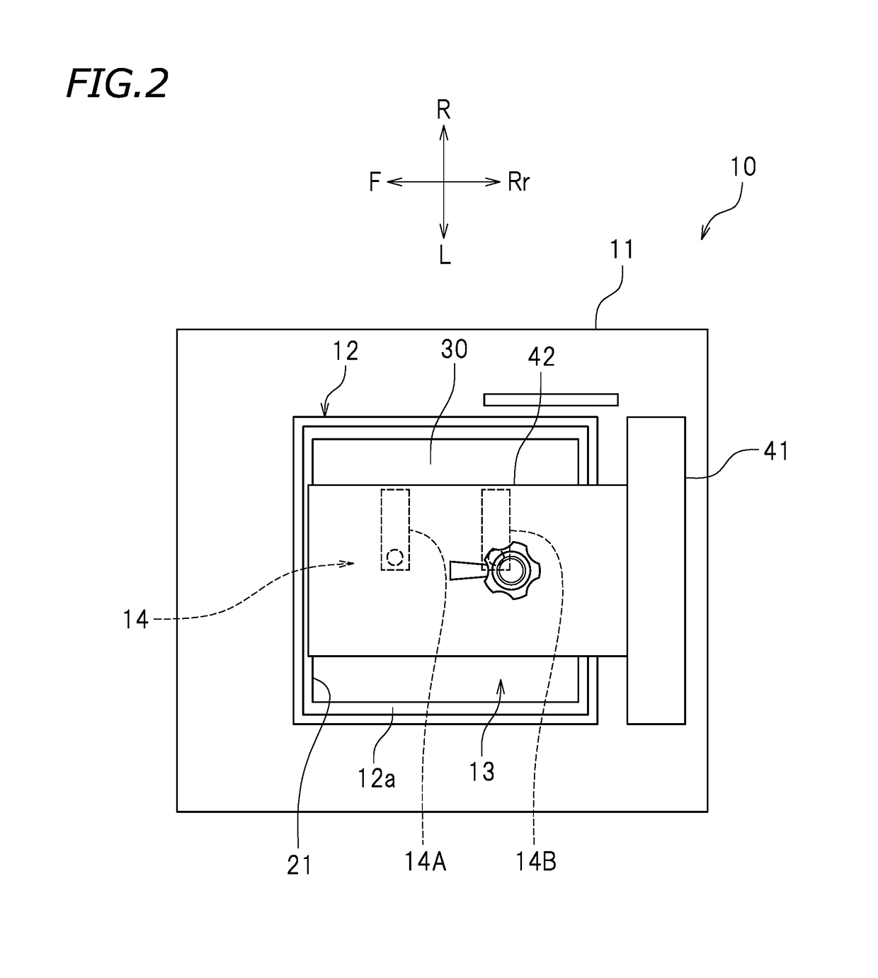
[0032]FIG. 1 is a cross-sectional view of a three-dimensional printing apparatus 10 according to a first preferred embodiment of the present invention. FIG. 2 is a plan view of the three-dimensional printing apparatus 10. The reference signs F, Rr, R, L, Up, and Dn in the drawings respectively represent front, rear, right, left, up, and down. The reference sign X in the drawings represents an X axis extending in the front-rear direction. The reference sign Y in the drawings represents a Y axis extending in the right-left direction. These directions are, however, defined merely for the sake of convenience and thus do not limit in any way how the three-dimensional printing apparatus 10 may be installed.

[0033]The three-dimensional printing apparatus 10 is configured to print a three-dimensional object. In accordance with cross-sectional images representing cross-sectional shapes of a three-dimensional object to be printed, the three-dimensional printing apparatus 10 cures liquid photo-...

second preferred embodiment

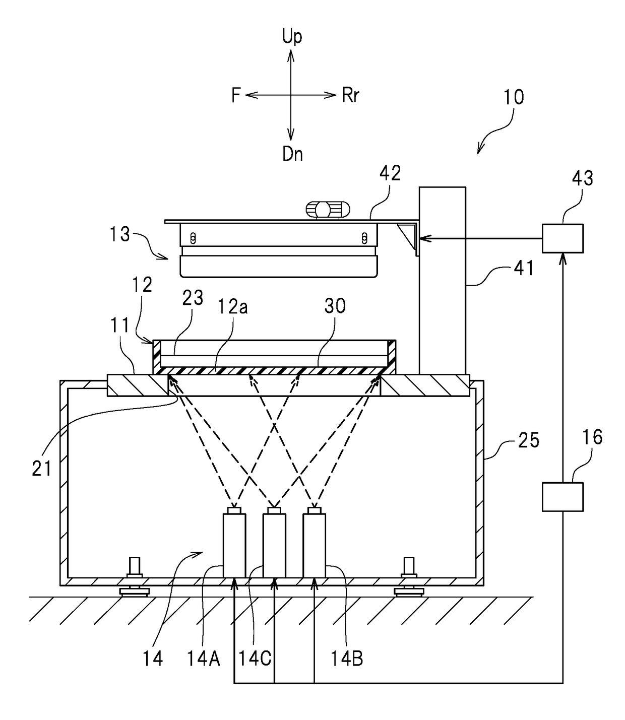
[0050]As illustrated in FIG. 6, the projector 14 preferably includes a third projector 14C in addition to the first projector 14A and the second projector 14B. The controller 16 is connected to the third projector 14C as well as to the first projector 14A and the second projector 14B. Similarly to the first projector 14A and the second projector 14B, the third projector 14C receives a cross-sectional image signal from the controller 16.

[0051]As illustrated in FIG. 7, the image projecting surface 30 preferably includes the first area 30A, the second area 30B adjacent to the first area 30A, the third area 30C adjacent to the second area 30B, a fourth area 30D adjacent to the first area 30A, a fifth area 30E adjacent to the second area 30B and the fourth area 30D, a sixth area 30F adjacent to the third area 30C and the fifth area 30E, and a seventh area 30G adjacent to the fourth area 30D, the fifth area 30E, and the sixth area 30F. The fourth to sixth areas 30D to 30F are located left...

third preferred embodiment

[0068]As illustrated in FIG. 11, the projector 14 preferably includes a fourth projector 14D and a fifth projector 14E in addition to the first projector 14A and the second projector 14B. The controller 16 is connected to the fourth projector 14D and the fifth projector 14E as well as to the first projector 14A and the second projector 14B. Similarly to the first projector 14A and the second projector 14B, the fourth projector 14D and the fifth projector 14E each receive a cross-sectional image signal from the controller 16. Component or elements similar to those in the second preferred embodiment will be omitted as unnecessary.

[0069]As illustrated in FIG. 12, the image projecting surface 30 preferably includes the first area 30A, the second area 30B adjacent to the first area 30A, the third area 30C adjacent to the second area 30B, the fourth area 30D adjacent to the first area 30A, the fifth area 30E adjacent to the second area 30B and the fourth area 30D, the sixth area 30F adjac...


PUM

PropertyMeasurementUnit
thicknessaaaaaaaaaa
areaaaaaaaaaaa
shapeaaaaaaaaaa

Abstract

A three-dimensional printing apparatus includes a controller to control first and second projectors that apply equal or substantially equal total amounts of optical energy. The controller performs first and second projecting operations. The first projecting operation involves simultaneously projecting first and second cross-sectional sub-images from the first projector onto first and second areas of an image projecting surface, respectively, and the second and third cross-sectional sub-images from the second projector onto the second and third areas of the image projecting surface, respectively. The second projecting operation involves simultaneously projecting the first cross-sectional sub-image from the first projector onto the first area and the third cross-sectional sub-image from the second projector onto the third area. The controller equalizes the number of times the first to third cross-sectional sub-images are to be respectively projected onto the first to third areas.

Description

[0001]This application claims priority to Patent Application No. 2015-122787 filed in Japan on Jun. 18, 2015, the entire contents of which are hereby incorporated by reference.BACKGROUND OF THE INVENTION[0002]1. Field of the Invention[0003]The present invention relates to three-dimensional printing apparatuses.[0004]2. Description of the Related Art[0005]A known three-dimensional printing apparatus applies light to liquid photo-curable resin stored in a tank so as to cure the photo-curable resin, thus printing a three-dimensional object.[0006]For example, JP 2003-39564 A discloses a three-dimensional printing apparatus including a table provided with an opening; a tank that is placed on the table and stores photo-curable resin; a raisable and lowerable holder disposed above the tank; and a projecting device disposed below the table. The projecting device projects a cross-sectional image representing a cross-sectional shape of a three-dimensional object to be printed. The cross-secti...

Claims


Application Information

Patent Timeline
Patent Type & Authority Patents(United States)
IPC IPC(8): B29C67/00B33Y30/00B33Y10/00
CPCB29C64/264B33Y10/00B33Y30/00B29C64/129
Inventor UEDA, JUNSAKURAI, TAKAYUKI
Owner ROLAND DG CORP
Learn More