Door stop assembly with decorative member

a technology of decorative members and doorstops, which is applied in the direction of door/window fittings, multi-purpose tools, construction, etc., can solve the problems that the aesthetics of a simple doorstop with a rubber tip are difficult to fit into a stylish interior

Inactive Publication Date: 2018-03-13
CATALANO KYLE
View PDF12 Cites 5 Cited by
  • Summary
  • Abstract
  • Description
  • Claims
  • Application Information

AI Technical Summary

Problems solved by technology

The aesthetics of a simple doorstop with a rubber tip are difficult to fit into a stylish interior.

Method used


Image

  • Door stop assembly with decorative member
  • Door stop assembly with decorative member
  • Door stop assembly with decorative member

Examples


Embodiment Construction

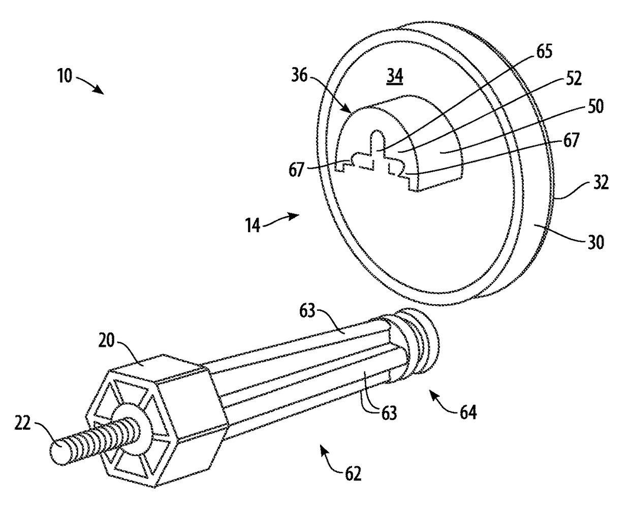
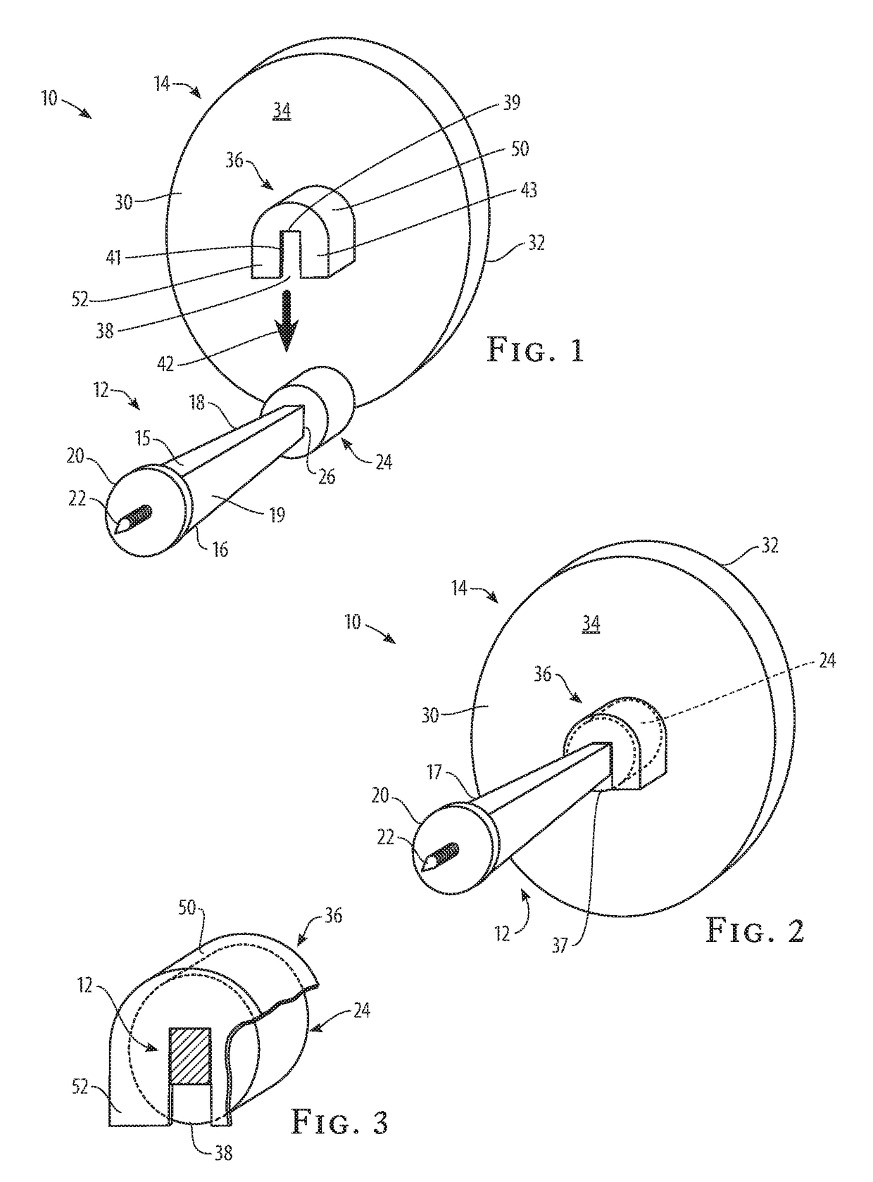
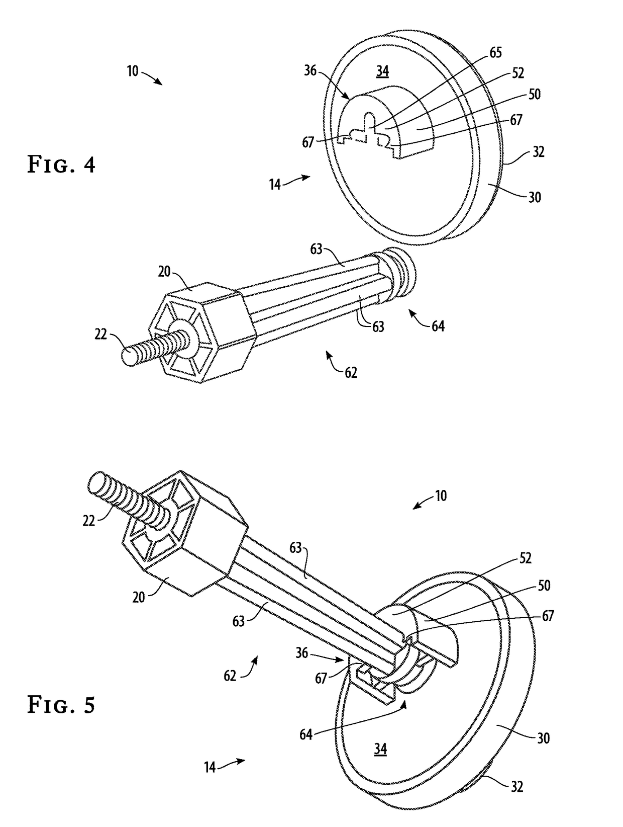
[0016]Turning now to the drawings in more detail, numeral 10 designates the door stop assembly according the present invention. The assembly 10 comprises an elongated post 12 and a detachable decorative member 14. The post 12 has a proximate end 16 and a distant end 18. The post 12 has a generally rectangular or square cross section between the proximate end 16 and the distant end 18. In one aspect of the invention, the post 12 is a solid rigid body, although it is envisioned that a hollow body may be used as well.

[0017]The proximate end 16 of the post 12 can be formed wider than the distant end 18 such that the post 12 tapers toward the distant end 18. Of course, the post 12 can be formed as a parallelepiped and have uniform thickness from the proximate end 16 to the distant end 18. The post 12 can be manufactured from metal, metal alloy, plastic, wood or other suitable material.

[0018]The proximate end 16 carries an end plate 20, which can be circular in cross section. The end plat...


PUM


Abstract

The invention relates to a doorstop having an interchangeable decorative member. The doorstop has an elongated post that is designed for securing behind an interior door of a building. The decorative member carries a fitting member on the back surface, which allows the decorative member to snap onto the post. Decorative indicia can be imprinted on the front surface of the decorative member.

Description

CROSS-REFERENCE TO RELATED APPLICATIONS[0001]This is a continuation-in-part application claiming priority from my co-pending application Ser. No. 14 / 304,878, filed in the United States Patent and Trademark Office on Jun. 13, 2014 for a “Door Stop Assembly with Decorative Member,” which is hereby incorporated by reference.BACKGROUND[0002]The present invention relates generally to a door stop assembly, and more particularly to a door stop assembly that has a detachable decorative member.[0003]Doorstops (or “door stops”) are extensively used in modern structures to prevent a door from opening too widely and damaging nearby walls with door handles. In some cases, a rubber cylinder or dome is screwed into the wall or the baseboard in the path of the door. On occasion, stops are used that are fitted at the midpoint of the door, as part of the central door-hinge. Such a stop is known as a “hinge stop.” The stops can be made in the form of a rod, a block of rubber-tipped metal, a spring, or...

Claims


Application Information

Patent Timeline
Patent Type & Authority Patents(United States)
IPC IPC(8): E05F5/06
CPCE05F5/06Y10T16/61
Inventor CATALANO, KYLE
Owner CATALANO KYLE
Why Eureka
Try Eureka