Exit lock assembly

a technology for exit locks and assembly parts, applied in the direction of building locks, construction fastening devices, construction, etc., can solve the problems of inconvenience and danger of escape, and achieve the effect of convenient opening

Inactive Publication Date: 2015-10-29
GIANNI INDS
View PDF4 Cites 5 Cited by
  • Summary
  • Abstract
  • Description
  • Claims
  • Application Information

AI Technical Summary

Benefits of technology

[0008]An objective of the present invention is to provide an exit lock assembly that the user can easy open when it are energized.

Problems solved by technology

However, when encountered an emergency, the user is often trying to open the exit 100 via the wrong push-press mode.
Thus, the aforementioned wrong push-press mode is likely to cause the exit 100 in a stuck case, and resulting in inconvenience and danger of escape.

Method used


Image

  • Exit lock assembly
  • Exit lock assembly
  • Exit lock assembly

Examples


first embodiment

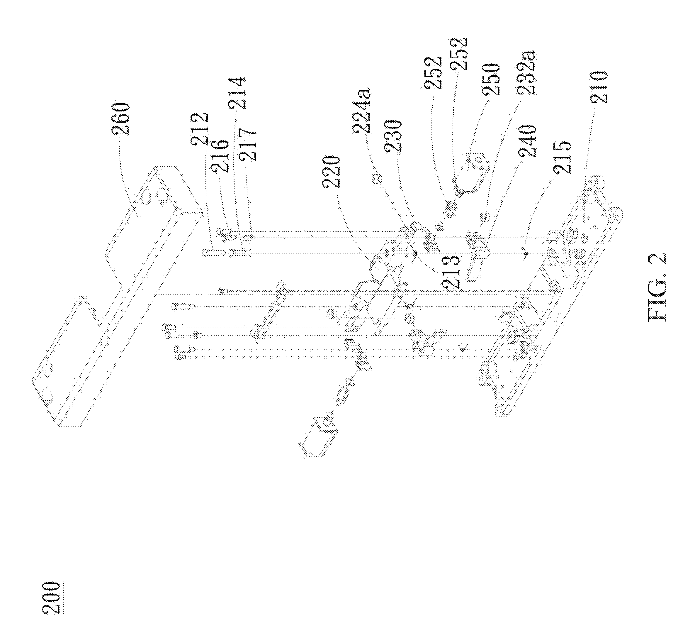
[0024]As shown in FIG. 2, the present invention of an exit lock assembly 200 comprises a base 210, two doorstops 220, two first links 230, two second links 240, two solenoid valves 250 and a cover 260.

[0025]With reference to FIGS. 3 and 4, the base 210 has a central area 210a and two side areas 210b disposed at two sides of the central area 210a. The central area 210a has two first axes 212 and two second axes 214 opposite to each other, and the side area 210b has two third axes 216.

[0026]The two doorstops 220 are disposed at the two first axes 212 of the central area 210a, and have a first end 222 and a second end 224 respectively. The two first links 230 are disposed at the two second axes 214 of the central area 210a, and have a third end 232 for holding the two second ends 224 of the two doorstops 220 respectively.

[0027]Further, with reference to FIG. 5, the two second links 240 are disposed at the two third axes 216 of the side areas 210b. The two second links 240 have a fourth...

second embodiment

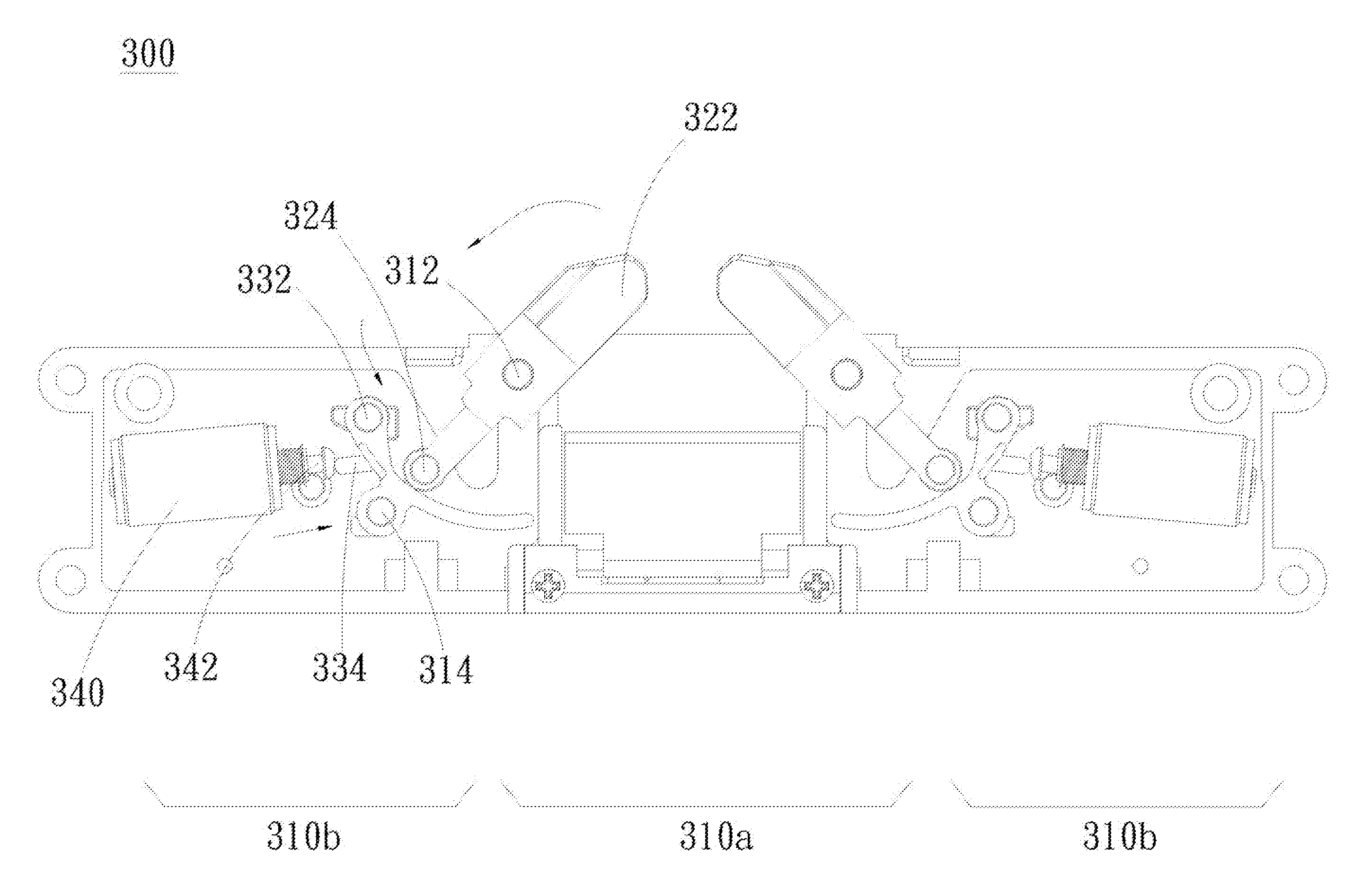
[0036]As shown in FIG. 8, the present invention of an exit lock assembly 300 comprises a base 310, two doorstops 320, two first links 330, two solenoid valves 340 and a cover 350.

[0037]With reference to FIGS. 9 and 10, the base 310 has a central area 310a and two side areas 310b disposed at two sides of the central area 310a, and the central area 310a has two first axes 312 and two second axes 314 opposite to each other.

[0038]The two doorstops 320 are disposed at the two first axes 312 of the central area 310a, and have a first end 322 and a second end 324 respectively.

[0039]The two first links 330 are disposed at the two second axes 314 of the central area 210a, each the first links 330 has a third end 332 and a projection 334, and the third end 332 is adapted to hold the second end 324 of the doorstop 320 respectively. The two solenoid valves 340 are disposed at the two side areas 310b, each the two solenoid valves 340 has a plug 342 respectively, and the plug 342 hold the project...


PUM


Abstract

An exit lock assembly is provided. The exit lock assembly comprises a base, two doorstops, two first links, two second links, two solenoid valves and a cover. The base and the cover are combined to form a receiving space to receive the two doorstops, the two first links, the two second links and the two solenoid valves. The doorstops are closed in an initial position when the solenoid valves are not energized. When the solenoid valves are energized, two plugs of the two solenoid valves move along the direction opposite a central area and drive two fifth ends of the two second links, two fourth ends of the two second links thus get away from the third ends of the first links, and the second end of the doorstop moves down and makes the doorstops in an open status.

Description

CROSS-REFERENCES TO RELATED APPLICATIONS[0001]Not applicable.BACKGROUND OF THE INVENTION[0002]1. Field of the Invention[0003]The present invention relates to an exit lock assembly, and more particularly, to an exit lock assembly capable of controlling the open status and close status of the doorstops via the solenoid valve.[0004]2. Descriptions of the Related Art[0005]As shown in FIG. 1, an exit 100 disposed on the public space in the prior art needs to be open via the press-push mode. However, when encountered an emergency, the user is often trying to open the exit 100 via the wrong push-press mode.[0006]Thus, the aforementioned wrong push-press mode is likely to cause the exit 100 in a stuck case, and resulting in inconvenience and danger of escape.[0007]In view of this, it is important to provide an exit lock assembly to avoid the above stuck case.SUMMARY OF THE INVENTION[0008]An objective of the present invention is to provide an exit lock assembly that the user can easy open wh...

Claims


Application Information

Patent Timeline
Patent Type & Authority Applications(United States)
IPC IPC(8): E05C3/00
CPCE05C3/002E05B47/0046E05B47/06E05B47/0607
Inventor CHANG, CHIH-CHUNG
Owner GIANNI INDS
Why Eureka
Try Eureka