A door stop

A technology for door stoppers and baffle plates, which can be used in door/window accessories, construction, building fastening devices, etc., and can solve problems such as trip hazards

Active Publication Date: 2018-09-28
HGT INNOVATIONS PTY LTD
View PDF15 Cites 6 Cited by
  • Summary
  • Abstract
  • Description
  • Claims
  • Application Information

AI Technical Summary

Problems solved by technology

[0006] Various existing wall loadable parts, floor loadable parts and door loadable parts present a tripping hazard

Method used


Image

  • A door stop
  • A door stop
  • A door stop

Examples


Embodiment Construction

[0074] The following examples are intended to show that reproducibility and comparison are possible. They are in no way intended to limit the scope of the present disclosure.

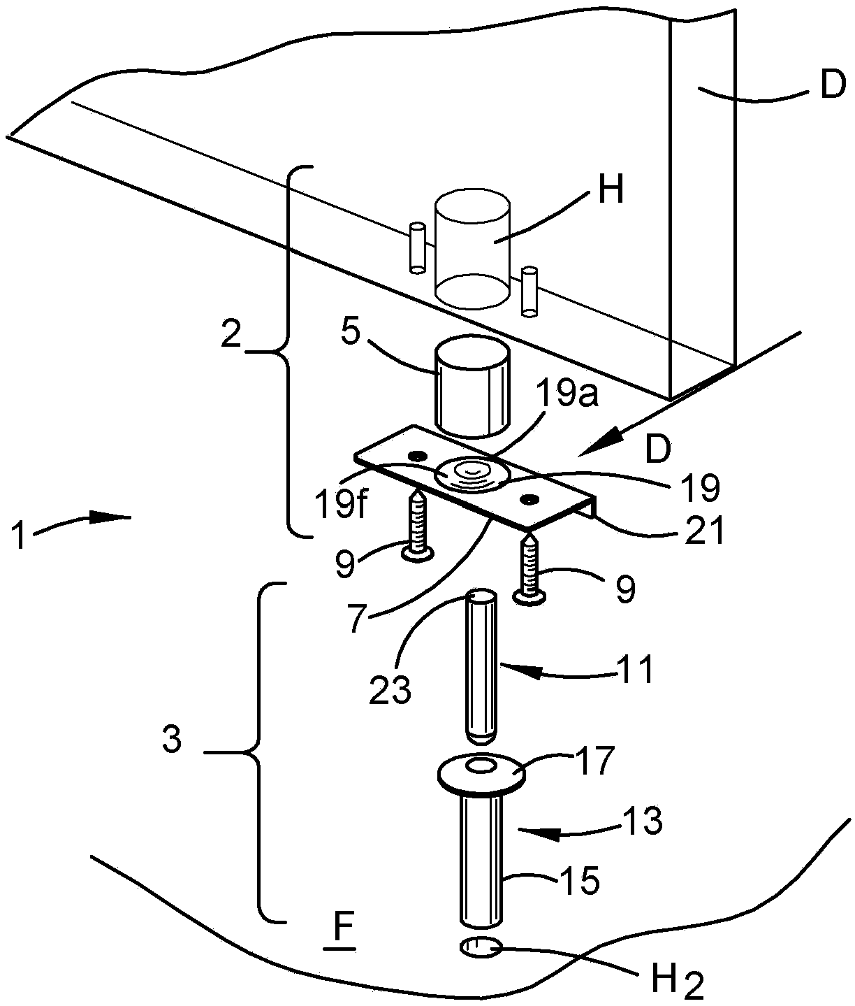
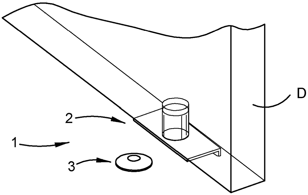
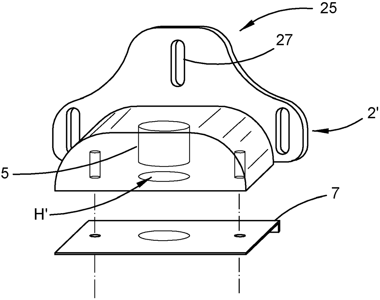
[0075] The door stopper 1 comprises a door loadable part 2 and a floor loadable part 3 . The door loadable part 2 includes a magnet 5 , a baffle 7 and two screws 9 . The floor loadable part 3 comprises a pin 11 and a guide bush 13 in which the pin 11 slides axially.

[0076] The magnet 5 is preferably a neodymium rare earth magnet and preferably has a strength of at least N35. In this example, the magnets are simple cylinders with slightly longer than square aspect ratios.

[0077] In order to install the door loadable part 2, a simple cylindrical hole H is drilled in the bottom of the door D. Hole H opens downward from the bottom level of door D. In this example, hole H is a simple cylindrical hole formed using a suitable drill such as an electric drill, and has a diameter of 25mm and a depth of a...


PUM


Abstract

A method of installing a door-bearable portion (2), for a door stop (1), to be carried by a door is disclosed. The door-bearable portion includes a magnet and a retaining member (7). The method includes drilling a hole in a bottom of the door; placing the magnet in the hole; and fastening the retaining member to the bottom of the door to at least partly span the opening to retain the magnet.

Description

technical field [0001] The present invention relates to a door stop (door stop, door brake). Background technique [0002] A door stop is a device used to stop a moving door. Some door stops are also used to hold doors in place. [0003] The existing door stop includes a wall loadable part and a door loadable part. The load-bearing portion of the wall is mounted to protrude outwardly from the skirting board of the wall. The load-carrying part of the door is mounted towards the lower edge of the door and on a main vertical face of the door. These parts cooperate magnetically to keep the door open against the wall. [0004] A magnet, as the word is used herein, is an item capable of magnetically attracting some other material, this attraction being called a magnetic cooperation, and each of the magnet and some other material being called a magnetically cooperating material. [0005] Sometimes it is convenient to park the door at a location where there is no convenient spo...

Claims


Application Information

Patent Timeline
Patent Type & Authority Applications(China)
IPC IPC(8): E05C17/56E05C19/16
CPCE05C17/56E05F5/06
Inventor 马克·安德鲁·塞勒凯丽·简·卢什克莱顿·史蒂夫·卢什
Owner HGT INNOVATIONS PTY LTD
Why Eureka
Try Eureka