Universal microwave waveguide joint and mechanically steerable microwave transmitter

a technology of universal microwave waveguide and mechanical steering, which is applied in the direction of waveguide devices, basic electric elements, antennas, etc., can solve the problems of increasing the total mass that must be driven to steer the antenna, the size and weight of the gimbaling mechanism are larger and heavier, etc., to reduce the size and power requirements of the azimuth and elevation rotation drive system, and simplify the antenna steering mechanism.

Active Publication Date: 2015-02-24
RAYTHEON CO
View PDF15 Cites 225 Cited by
  • Summary
  • Abstract
  • Description
  • Claims
  • Application Information

AI Technical Summary

Benefits of technology

[0010]The present invention provides a universal microwave waveguide joint (“universal joint”) that allows for simultaneous 3-axis rotation, and 3-dimensional translation between the transmitter's antenna, and the stationary source. As such, the universal joint does not have to be physically aligned with the azimuth and elevation rotation axis of the antenna and mounted on the gimbal support, greatly simplifying the antenna steering mechanism. The universal joint allows the antenna to be mass-balanced in relation to the azimuth and elevation axis without adding any additional counter weights, thus reducing the size and power requirements of the azimuth and elevation rotation drive systems.
[0011]In an embodiment a mechanically steerable microwave transmitter system comprises a stationary source of a beam of microwave radiation in a first waveguide mode, an antenna for receiving the beam of microwave radiation from a second waveguide mode and then transmitting free-space radiation, and a gimbal support that supports only the antenna. The first and second waveguide modes may, for example, be the dominant rectangular TE10 mode. The gimbal support is operable to rotate the antenna about azimuth and elevation, axes through the center of mass

Problems solved by technology

Two important problems in the design of a gimbaled transmitter are coupling the beam from the source to the antenna and minimizing the beam loss between the source and the antenna.
This approach is not desirable for many trans

Method used


Image

  • Universal microwave waveguide joint and mechanically steerable microwave transmitter
  • Universal microwave waveguide joint and mechanically steerable microwave transmitter
  • Universal microwave waveguide joint and mechanically steerable microwave transmitter

Examples


Embodiment Construction

[0019]The present invention provides a universal microwave waveguide joint (“universal joint”) that allows for simultaneous 3-axis rotation and 3-dimensional translation between the mechanically steerable transmitter's antenna and the stationary source. As such, the universal joint does not have to be physically aligned with the azimuth and elevation rotation axis of the antenna and mounted on the gimbal support, greatly simplifying the antenna steering mechanism. The universal joint allows the antenna to be mass-balanced in relation to the azimuth and elevation axis without adding any additional counter weights, thus reducing the size and power requirements of the azimuth and elevation rotation drive systems.

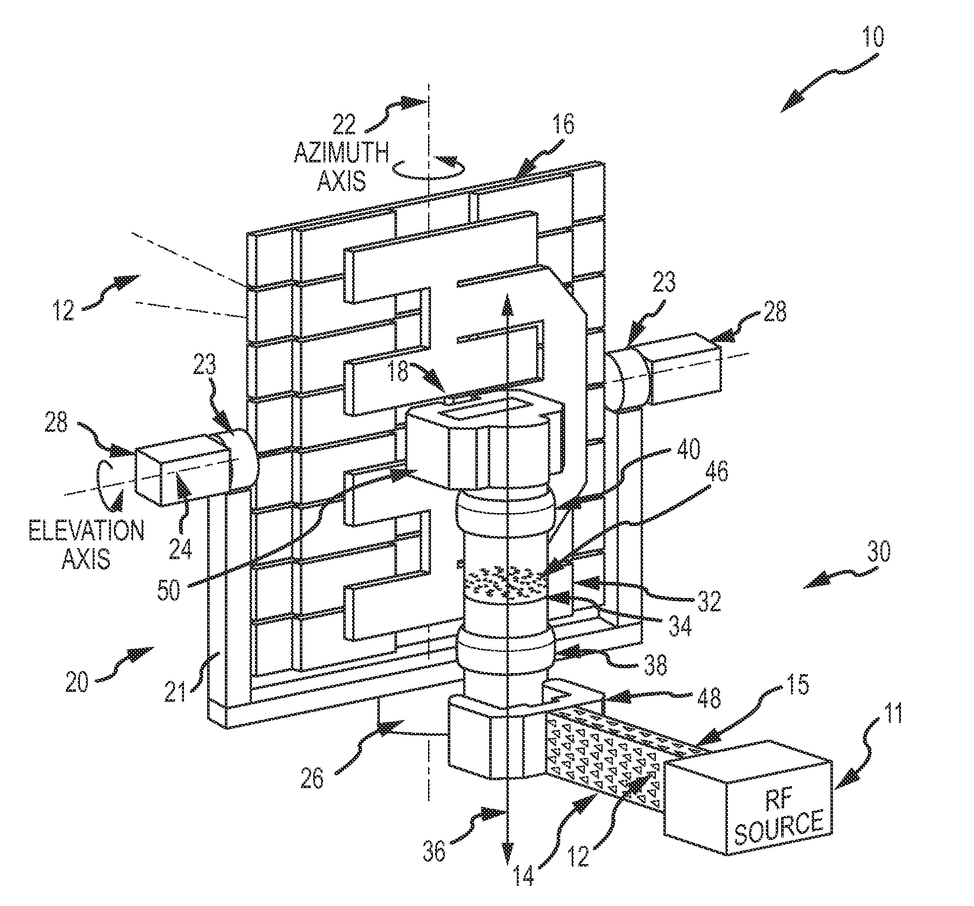
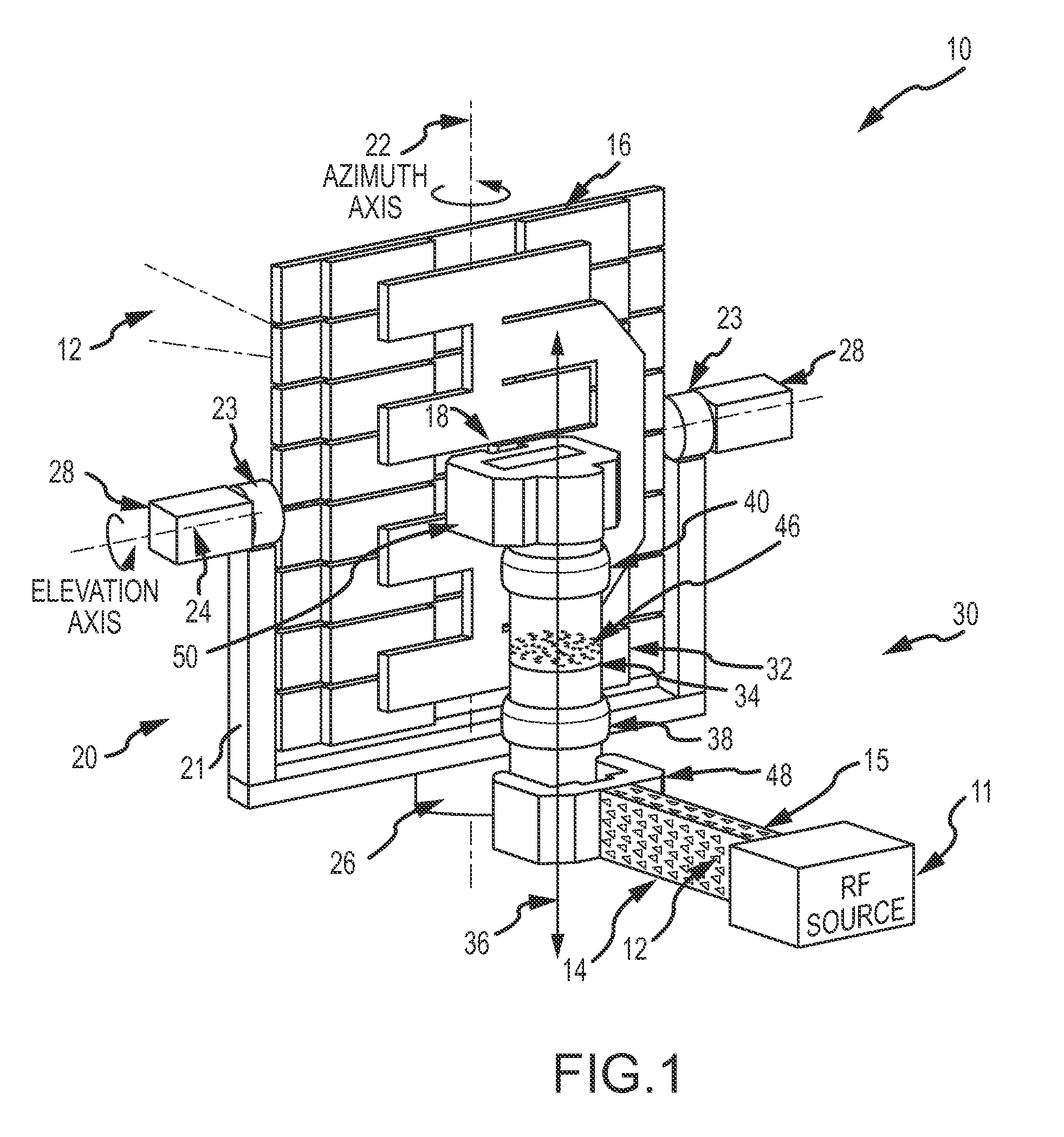
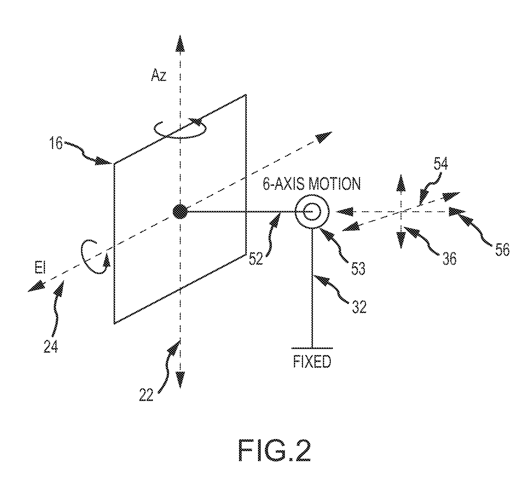
[0020]Referring now to FIGS. 1 and 2, an embodiment of a mechanically steerable transmitter 10 includes a stationary source 11 that generates a beam 12 of microwave radiation that propagates in a first waveguide mode 14 e.g. rectangular TE10, in a waveguide 15, an antenna 16 (e...


PUM


Abstract

A universal joint comprising a pair of circular waveguide ball-joints and a slip-joint allows for simultaneous 3-axis rotation and 3-dimensional translation between an antenna and a stationary source. As such, the universal joint does not have to be physically aligned with the azimuth, and elevation, rotation axis of the antenna and mounted on the gimbal support, greatly simplifying the antenna steering mechanism. The universal joint allows the antenna to be mass-balanced in relation to the azimuth and elevation axis without adding any additional counter weights, thus reducing the size and power requirements of the azimuth and elevation rotation drive systems. Additional ball-joints may be provided to increase the allowed range of motion of the antenna.

Description

BACKGROUND OF THE INVENTION[0001]1. Field of the Invention[0002]This invention relates to microwave rotating waveguide joints that transmit microwave energy from a stationary source to feed a mechanically steerable microwave transmitter, and more particularly to a universal microwave waveguide joint that allows for simultaneous 3-axis rotation and 3-dimensional translation between the transmitter's antenna and the stationary source.[0003]2. Description of the Related Art[0004]A mechanically steerable microwave transmitter includes a source that generates a beam of microwave radiation, an antenna that projects the beam, through foe space, and a gimbal mechanism, that rotates the antenna about the Azimuth and Elevation axes to point the beam in any direction of a hemisphere and a waveguide to direct the beam from the output of the stationary source to the antenna feed. Exemplary sources may include a magnetron or klystron that produce a high power beam of microwave radiation having a ...

Claims


Application Information

Patent Timeline
IPC IPC(8): H01Q13/00
CPCH01P1/06H01P1/061H01P1/065
Inventor BROWN, KENNETH W.
Owner RAYTHEON CO
Why Eureka
Try Eureka