Door stop structurally combined with a demountable door hinge

a door stop and demountable technology, applied in the direction of doors, wing accessories, roofs, etc., can solve the problems of increasing the probability of encountering unfavourable tolerance pairings, increasing noise production, and not being able to standardize the door stop and its componen

Inactive Publication Date: 2002-11-12
ED SCHARWACHTER GMBH & CO KG
View PDF10 Cites 5 Cited by
  • Summary
  • Abstract
  • Description
  • Claims
  • Application Information

AI Technical Summary

Problems solved by technology

Door stops of this type are therefore basically afflicted with a production outlay which is still excessively high and at the same time with certain uncertainties with regard to specified holding positions of the door always being maintained.
Moreover, the result of the number of components required overall for the door stop is that there is an increase in the probability of encountering unfavourable tolerance pairings and therefore, obviously, the increased production of sources of noise which can be attributed to unfavourable tolerance pairings within the door stop.
However, the disadvantage of it not being possible to standardize the door stop and its component is particularly serious.
Although such door-braking and stopping devices integrated in a door hinge are distinguished by an extremely small installation space requirement and also only require a minimum number of individual parts, they are afflicted with the disadvantage that the machining of the hinge half through whose gudgeon the hinge pin passes with bearing clearance is extremely complicated.

Method used


Image

  • Door stop structurally combined with a demountable door hinge
  • Door stop structurally combined with a demountable door hinge
  • Door stop structurally combined with a demountable door hinge

Examples


Embodiment Construction

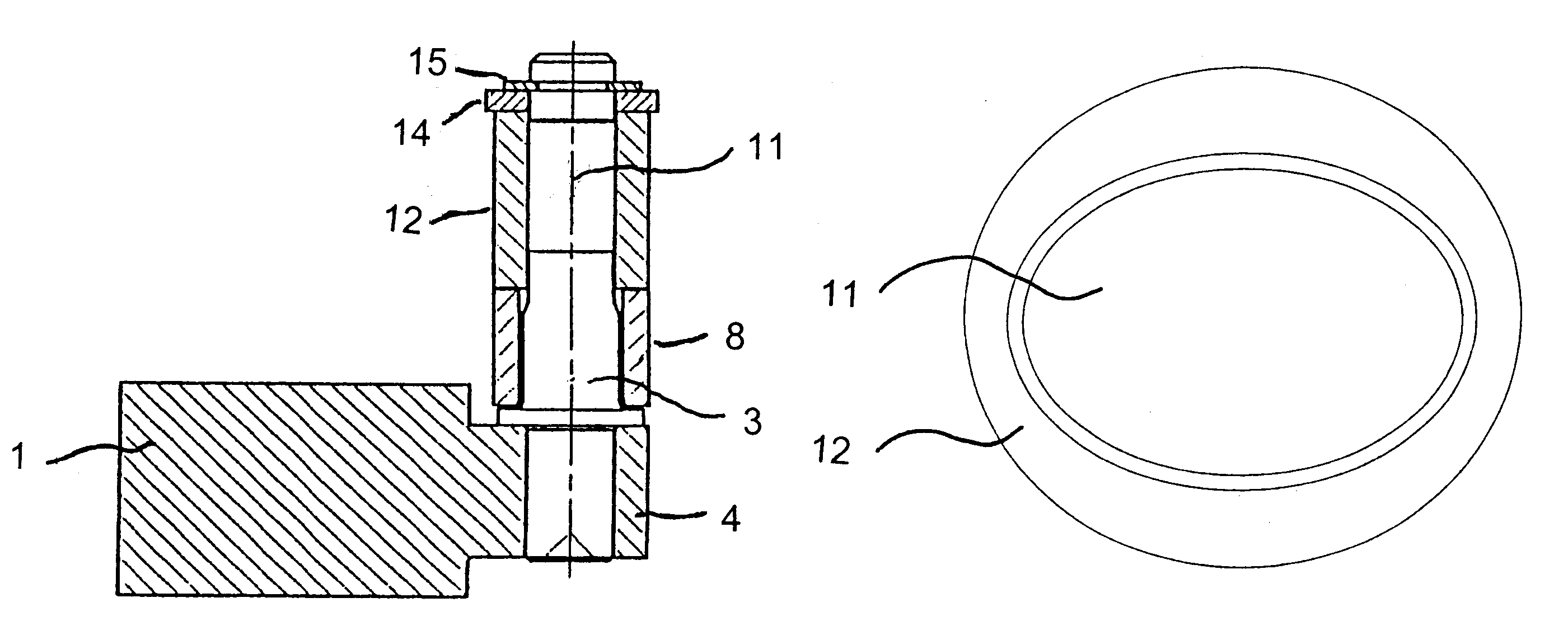
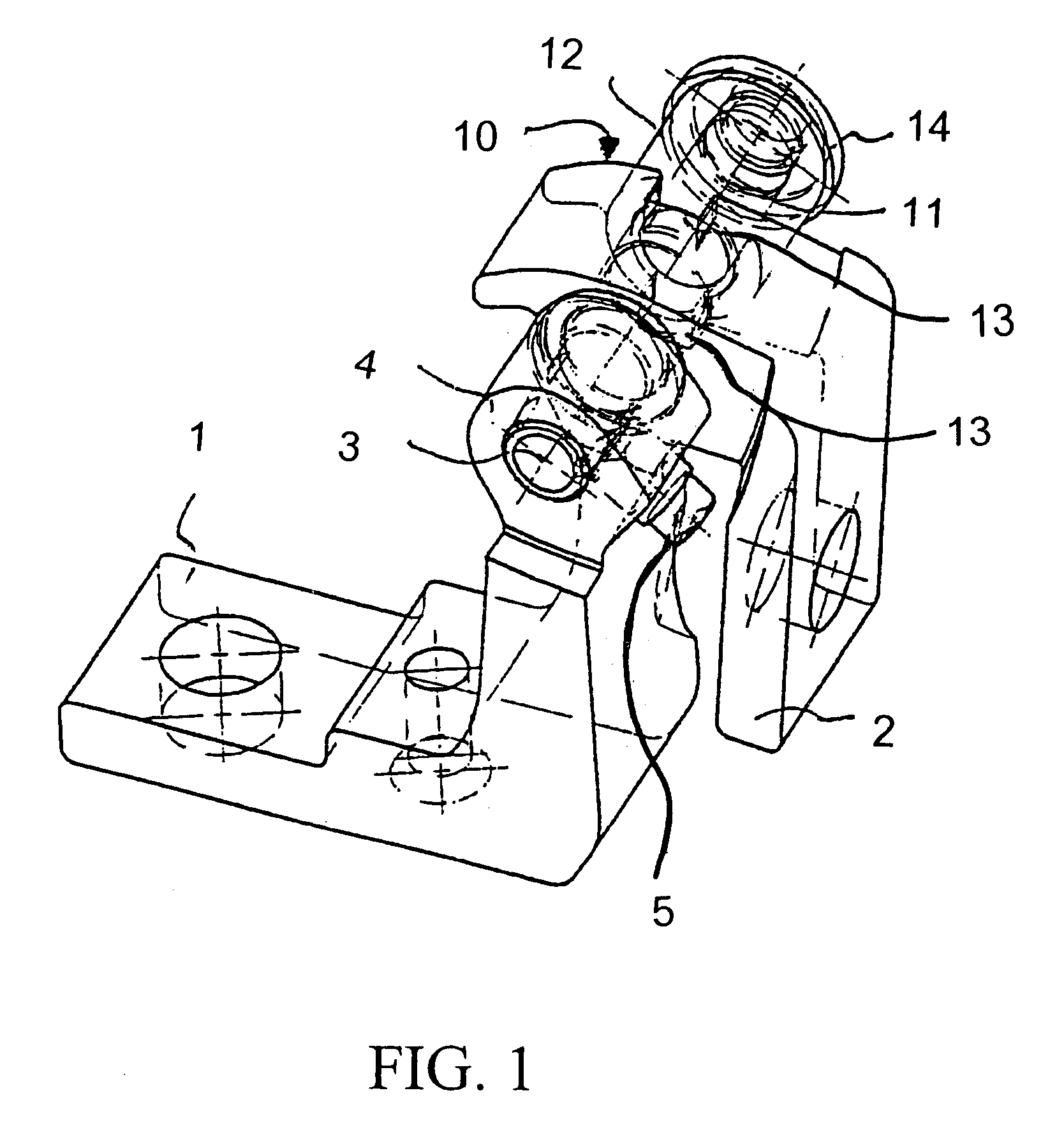
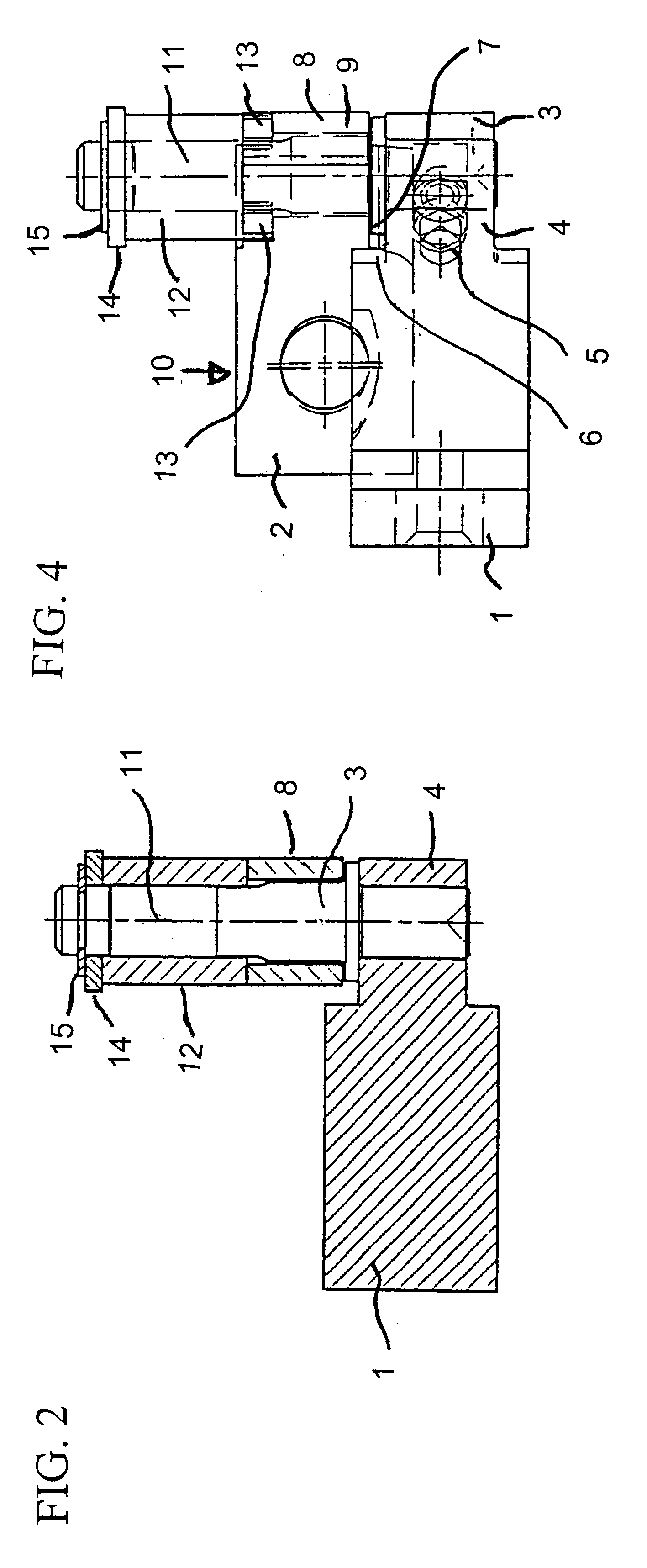
As shown in FIGS. 1 through 5, the demountable door hinge comprises a first hinge half 1, which can act on the one door assembly part, which is not illustrated in greater detail in the drawing, and a second hinge half 2, which acts on the other door assembly part, which is likewise not illustrated in greater detail in the drawing, and also a hinge pin 3 which pivotably connects the two hinge halves 1 and 2 to each other. In the gudgeon 4 of the first hinge half 1 the hinge pin 3 is secured in a rotationally secure manner by means of an interference fit and a radial screw 5.

The hinge pin 3 has a radially protruding collar 6 with which it fits over the inner joint side 7 of the hinge half 1.

In the gudgeon 8 of the second hinge half 2 the hinge pin 3 is mounted with a running fit in a freely rotatable manner by means of a bearing bushing 9 made of maintenance-free bearing material.

The hinge pin 3 has a length section 11 which protrudes over the outer joint side 10 of the second hinge h...


PUM


Abstract

The invention relates to a door stop for motor vehicle doors which is integrated with a demountable door hinge. The door hinge is comprised of two hinge halves (1, 2) and a hinge pin (3) which is accommodated in hinge half (2) with a running fit and in the other hinge half (1) such that it can be lifted off without turning. The door stop comprises braking or holding means which are radially aligned in relation to the hinge pin axis and which interact with stopping means concentrically arranged in relation to the hinge pin axis. The door stop assembly is primarily accommodated in a door stop housing (12). Said door stop housing is placed, in an axial projection (11) of the hinge axis. The hinge pin is mounted with a running fit in the hinge half (2). According to the invention, the hinge pin (3) is connected to a complementary non-circular form of the inner peripheral wall of the door stop housing (12) which is connected to the respective hinge half (2) whose knuckle intersperses the hinge pin with bearing clearance. Said hinge pin comprises a curvature contour of the cross-section thereof, said contour deviating from the pure circular form, over at least part of the longitudinal area (11) of the hinge pin which engages inside the door stop housing (12).

Description

The invention relates to a door stop structurally combined with a demountable door hinge for motor-vehicle doors, the door hinge comprising a first hinge half which can act upon the one door assembly part, door or pillar, and a second hinge half which can act upon the other door assembly part, and also a hinge pin which is held in the one hinge half with a running fit and in the other hinge half in a manner such that it can be lifted off in a rotationally secure manner, and the door stop comprising braking or holding means which are arranged aligned radially with respect to the hinge-pin axis and which interact with abutment means arranged concentrically with respect to the hinge-pin axis, and being accommodated in its entirety in a door stop housing which is placed, in an axial extension of the hinge axis, onto that hinge half in which the hinge pin is mounted with a running fit.BACKGROUND INFORMATIONAlthough door stops of this type which are structurally combined with a door hinge...

Claims


Application Information

Patent Timeline
Patent Type & Authority Patents(United States)
IPC IPC(8): E05D11/00E05D11/10E05D11/08
CPCE05D11/084E05D11/1057Y10T16/557E05Y2900/531Y10T16/54038E05D2011/1035
Inventor KREMER, JOHANNESMAGNUS, NILS
Owner ED SCHARWACHTER GMBH & CO KG
Why Eureka
Try Eureka