Child Safe Door, Frame and Hinge Assembly

a technology for hinges and doors, applied in the direction of hinges, door/window fittings, wing arrangements, etc., can solve the problems of finger injury to the hinge side of the door, many dangers to users and others, and more serious consequences

Active Publication Date: 2010-12-16
BOYER GEORGE AKOS
View PDF31 Cites 6 Cited by
  • Summary
  • Abstract
  • Description
  • Claims
  • Application Information

AI Technical Summary

Benefits of technology

[0022]It is another object of the present invention to provide a door, frame and hinge assembly that does not create a gap between the hinge side of the door and the frame as the door is opened, in the area from which the door opens outwardly and which is very easily accessible.
[0023]It is yet another object of the present invention to provide a door, frame and hinge assembly that does not create a gap between the hinge side of the door and the frame as the door is opened, in the area into which the door opens and which is not as easily accessible, but still remains somewhat accessible.
[0027](c) hinge means connecting the hinge side of the door to the hinge side of the frame through a hinge pivot point,wherein the convexly curved surface extends beyond the location of the hinge pivot point towards, and locates within, the cavity, so as to allow the door to open without a gap being created between the hinge side of the door and the frame that may cause finger-pinch injury.

Problems solved by technology

Doors pose many dangers to users and to others who may come into close proximity to them.
When, say, a finger is caught in the gap at the handle side of a door, the injury may involve simple bruising if the door shuts relatively slowly or may involve more serious consequences if the door is slammed shut by a person or is driven by a strong draught with high velocity.
However, the injury to a finger caught in the gap at the hinge side of the door may be even more severe.
A prominent part of the cause of such accidents is the design of the door itself.
Even a slight breeze blowing a door shut could cause a serious crushing injury to a finger caught in the gap at the hinge side.
Its presence poses a greater problem in terms of the risk of finger-pinch injury than any functional benefit it might have.
Because of the smaller width and the metallic nature of the hinge side doorstop, the cutting and trapping effects on a finger placed against the hinge side door jamb will be more severe than that for wooden door frames, acting like a bolt cutter.
These problems may be exacerbated if the door has an automatic (spring loaded) return system.
Far worse consequences may arise where fingers are trapped by metal security doors, which typically have knife-like inner edges instead of the squared corner, inner edges of other doors, and so have a guillotine-like action.
Although functionally effective, these devices require regular maintenance and replacement from the wear and tear they experience on a daily basis.
Also, they can be easily damaged or removed, and have an aesthetically poor appearance.
These factors have led to generally low market penetration for these devices.
It has been found by the present inventor that none of the prior art devices and methods for preventing finger-pinch injury at the hinge side of a door are reliable over the life of the door because they can, in certain circumstances, be separated from the door or fail functionally.
Although that assembly prevents a gap from being created between the hinge side of the door and the frame as the door is opened up to an angle of about 90 degrees, it requires complex, prefabricated hinge members to be fitted to, and extend along the full height of, adjacent sides of the door and frame.
There may also be the problem that the slender, curved guard portion of the projecting part of the frame, which needs to have at least some part of it engaged within the cavity at the hinged side of the door to prevent finger-pinch injury, may be distorted in shape as a result of misuse or impact, and no longer serve its function.
Other attempts at utilizing complementary shaped surfaces between fixed and rotating sides of structures to prevent finger-pinch injury have also not been able to allow for such prevention up to 90 degrees, or just beyond that angle for corner located doors, but have a much shorter range of protected opening, usually no more than about 60 degrees depending on the relative structures of the projecting part and the cavity.

Method used


Image

  • Child Safe Door, Frame and Hinge Assembly
  • Child Safe Door, Frame and Hinge Assembly
  • Child Safe Door, Frame and Hinge Assembly

Examples


Embodiment Construction

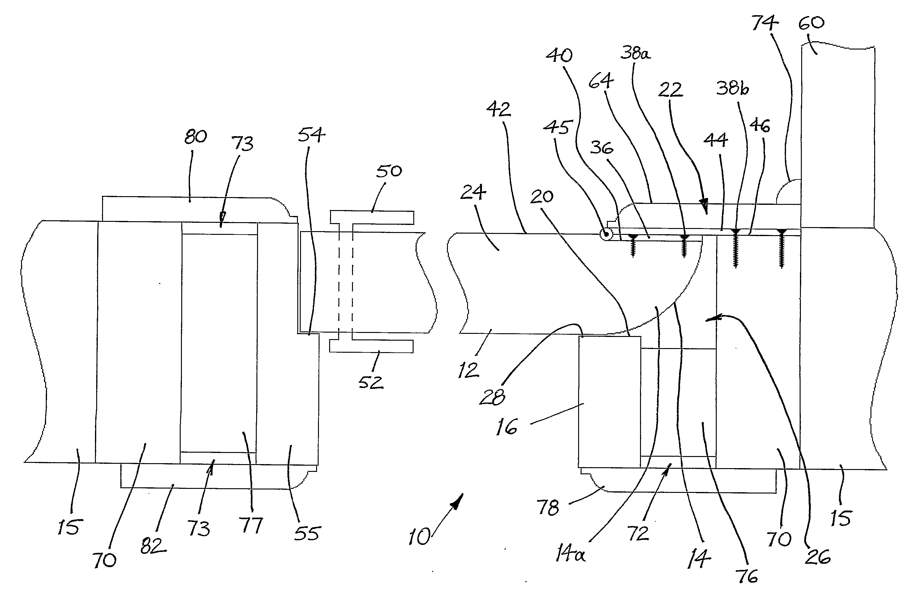
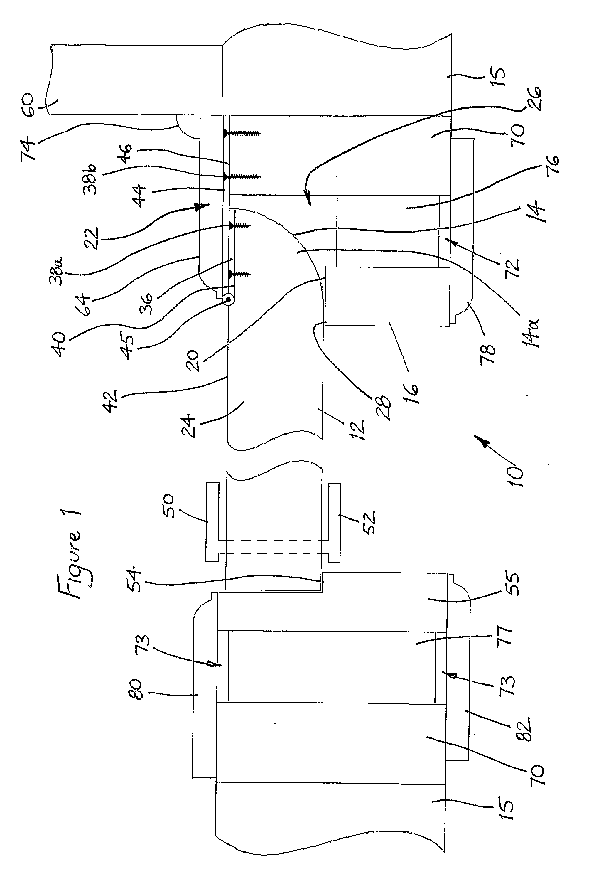
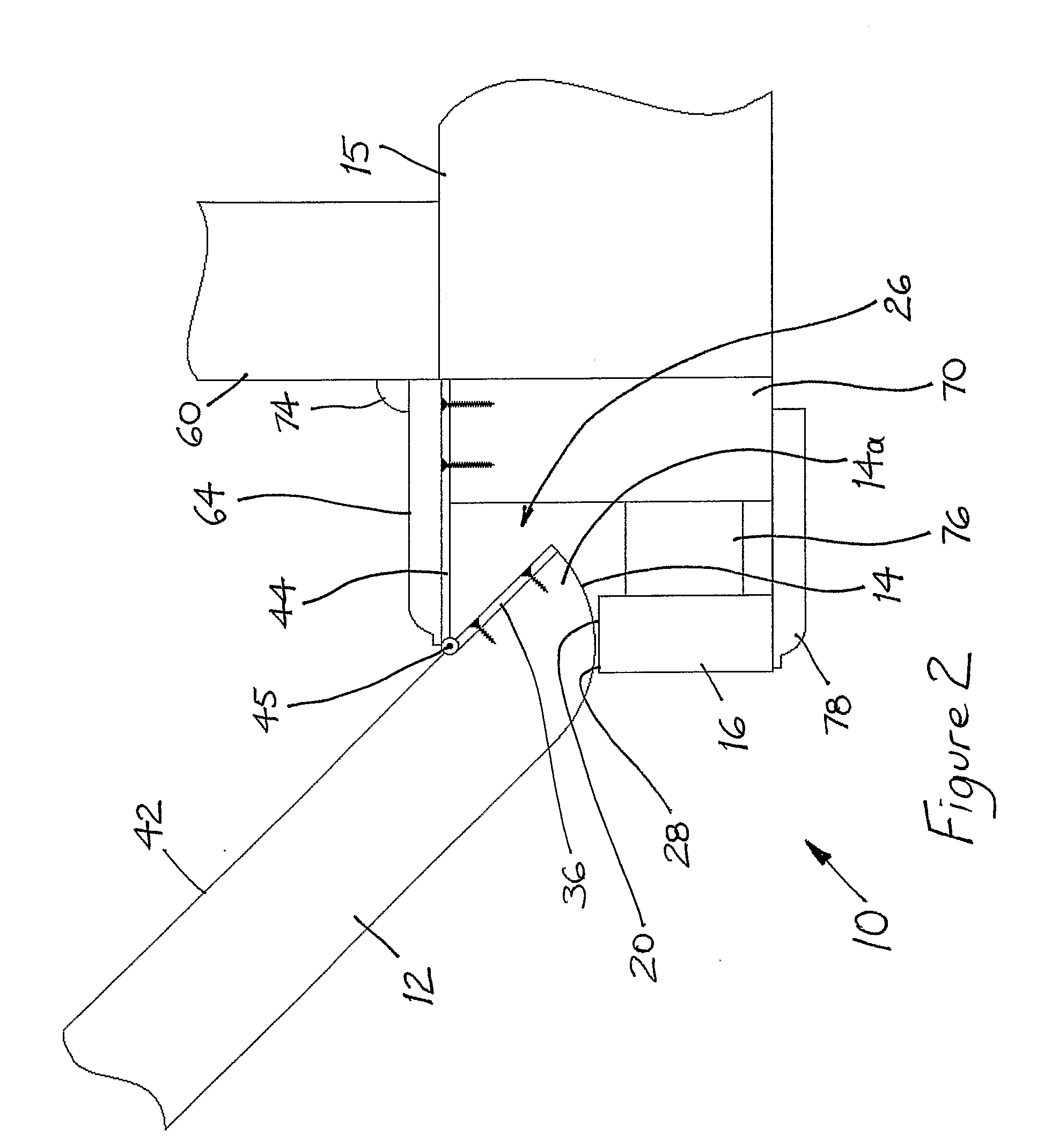
[0046]With reference now to the above summarized drawings of FIGS. 1 to 8, a door, frame and hinge assembly embodying the principles and concepts of the present invention will now be described.

[0047]The door, frame and hinge assembly 10 shown in FIG. 1 includes a door 12 having a hinge side defined by a convexly curved surface 14, a frame mounted to a wall 15, the frame being formed of a hinge side wall stud 70, vertically spaced apart packing blocks 76, and a hinge side door jamb 16. The hinge side door jamb 16 defines a hinge side doorstop face 20 of sufficient width (or of sufficient distance from the wall stud 70) to allow the door 12 to open without a gap being created between the hinge side of the door 12 and the door jamb 16 that may cause finger-pinch injury. The assembly 10 also includes hinge means 22 connecting the door 12 to the wall stud 70.

[0048]The convexly curved surface 14 defining the hinge side of the door is, in this embodiment, the curved surface of a cylindrica...


PUM


Abstract

A door, frame and hinge assembly (10) includes a door (12) having a main body (24) with a hinge side defined by a convexly curved surface (14), and a frame (16, 70, 76) having a hinge side defined by a door jamb cavity (26). A hinge means (22) connects the hinge side of the door (12) to the hinge side of the frame (16, 70, 76) through a hinge pivot point (45). The convexly curved surface (14) extends beyond the location of the hinge pivot point (45) towards, and locates within, the cavity (26), so as to allow the door (12) to open without a gap being created between the hinge side of the door and the frame that may cause finger-pinch injury. The convexly curved surface (14) may be the curved surface of a cylindrical quarter segment (14a). The hinge side of the door (12) is formed integrally or continuously with the main body (24) of the door and extends into the door jamb cavity (26). The cavity (26) is defined at one side by the doorstop face (20) of a hinge side door jamb (16) and at the opposite side by a stationary wing (44) of the hinge means, with an innermost side of the cavity being defined by a hinge side wall stud (70).

Description

FIELD OF THE INVENTION[0001]The present invention relates to a door, frame and hinge assembly and, in particular, to a finger-pinch injury preventing assembly at the hinge side of a door.[0002]Although the background, objects and preferred embodiments of the invention will be hereinafter described with reference to a door, frame and hinge assembly for use in buildings, it is to be understood that the invention is not limited thereto but has wider application. For example, the door, frame and hinge assembly may be used in vehicles and like mobile structures.[0003]It is to be understood that the terminology employed herein is for the purpose of description only and should not be regarded as limiting. For instance, the terms “comprising” or “comprises” are to be understood as meaning “including”, unless otherwise stated.[0004]Also, the term “door” is to be understood as including any device, whether or not it is “door-like”, that can be swung open and shut by hinges, such as hinged win...

Claims


Application Information

Patent Timeline
Patent Type & Authority Applications(United States)
IPC IPC(8): E06B3/34E06B7/36
CPCE06B7/36
Inventor BOYER, GEORGE AKOS
Owner BOYER GEORGE AKOS
Why Eureka
Try Eureka