
Plenoptic imaging device

a technology of optical imaging and plenum, which is applied in the field of plenum imaging devices, can solve the problems of limited utility, poor inversion step, and inferior throughpu

Active Publication Date: 2018-04-03
KLENS GMBH
View PDF26 Cites 2 Cited by
  • Summary
  • Abstract
  • Description
  • Claims
  • Application Information

AI Technical Summary

Benefits of technology

[0013]It is therefore an object of the invention to enable snapshot imaging of the plenoptic dimensions of an image, however, while avoiding the necessity of custom camera designs. It is a further object of the invention to design an optical element that can reversibly be combined with any existing imaging device, such as a DLR, a mobile phone or tablet camera, an industrial camera, cinema camera or a microscope, but can easily be removed for normal use, thereby enabling wide-spread adoption of plenoptic imaging by users.BRIEF SUMMARY OF THE INVENTION
[0015]According to the invention, a reversible modification of standard camera hardware to flexibly acquire several plenoptic dimensions, such as wavelength, time, and direction is achieved by a simple optical design. In addition, it can be used for high dynamic range and polarization imaging, in photo and video cameras alike.
[0016]The inventive device physically multiplies an optical image by means of repeated mirror operations, which makes it suitable for time-crucial shots. The resulting array of equivalent images maintains the plenoptic properties of the physical image. These copies are projected into a plane where they are optically pre-filtered and then imaged by a 1:1 imaging unit onto the sensor of a standard camera. This optical element can easily and reversibly be inserted between the lens and body of a standard camera, converting it into a high dynamic range, multispectral, polarization, light-field imaging unit or combinations thereof, depending on the configuration of the proposed optical element.
[0017]The invention comprises a novel optical design using a direct spatial multiplexing scheme for monocular snapshot plenoptic imaging. It relies on inter-reflections within mirror systems and can be added nonpermanently to any standard camera and be reconfigured to image different plenoptic dimensions in a unified design. In contrast to other approaches, the light-field design according to the invention is most suitable for imaging at a low directional, but high spatial resolution. High-quality refocusing and view-point changes are possible and in unprecedented large virtual apertures at a high spatial resolution can be achieved.
[0018]Comparing to the established lenslet-based design, the inventive solution explores an orthogonal end of the design space. While lenslet-based light-field cameras offer a high angular resolution, their spatial resolution is limited and has to be interpolated to enable an acceptable image size. Contrary, the inventive design is most suitable for imaging at a high spatial resolution with a low number of angular views. Nevertheless, the angular resolution has to be interpolated to enable convincing refocusing effects. These trade-offs are an inherent feature of the two designs. Decreasing the angular resolution to gain spatial resolution is difficult for the lenslet-based design since the size of the micro lenses represents a limiting factor. In addition, color imaging with color-filter arrays would become infeasible when approaching low angular resolutions. In contrast, increasing the number of angular views in the inventive design makes the device size less feasible. A unique advantage of the inventive design is that the depth of field of the individual light-field views can be regulated by the aperture of the pickup lens. Light field aliasing can therefore be controlled by the user. The maximum achievable parallax is in both cases limited by the aperture size of the main lens and this performance parameter is the same for both designs.

Problems solved by technology

Optical flow [Horn and Schunck 1981] can be applied, but in practice, it is of limited utility since it is based on the brightness constancy assumption which may be violated when different optical pre-filters are being used.
Often, this inversion step is ill-posed and has to be regularized using prior information about the signal.
2008], even though the latter leads to a lower SNR because the light throughput is inferior.

Method used


Image

  • Plenoptic imaging device
  • Plenoptic imaging device
  • Plenoptic imaging device

Examples


first embodiment

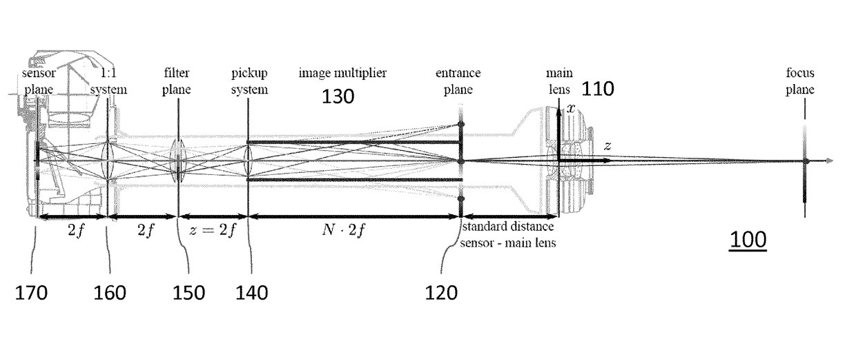
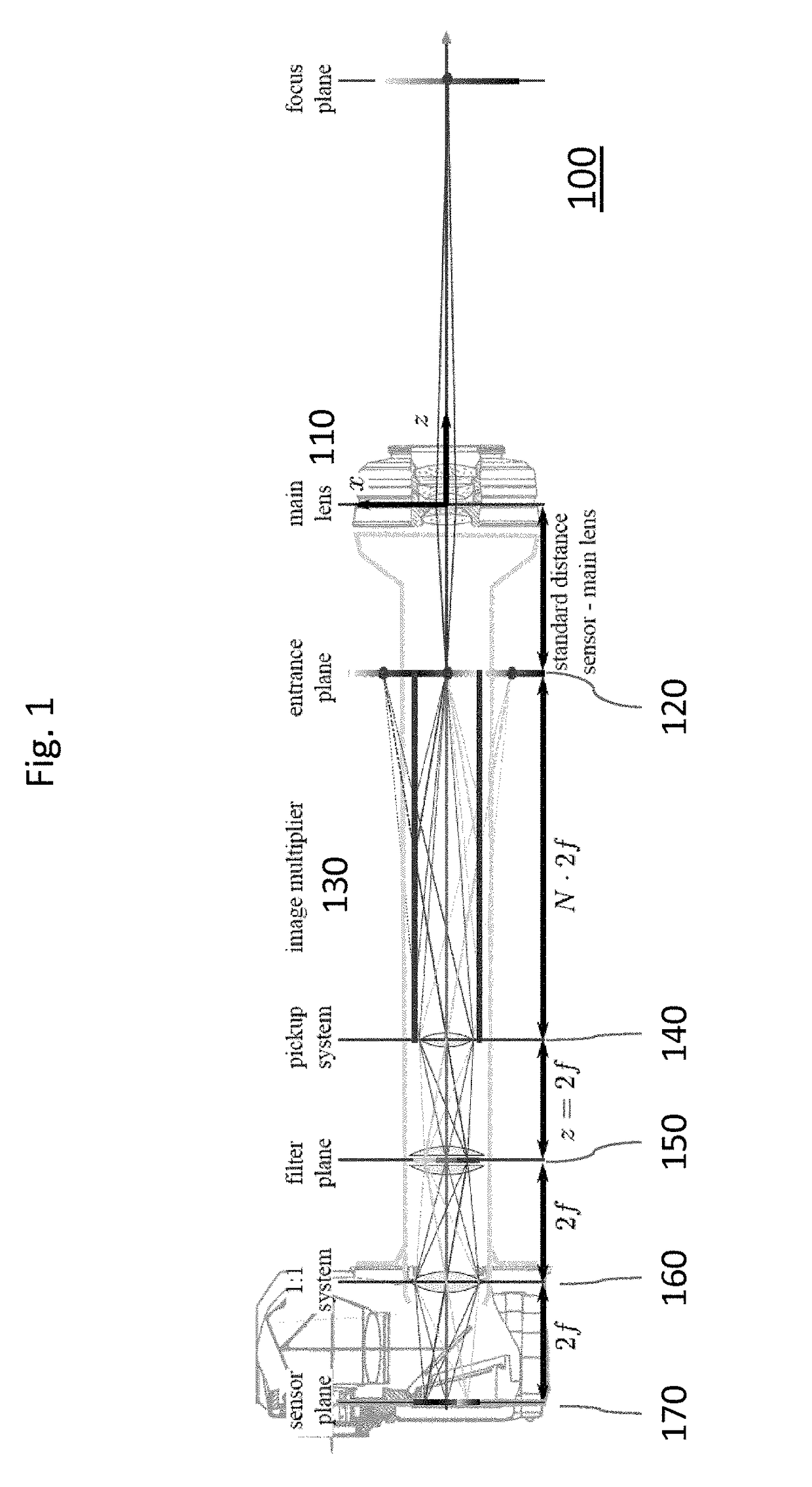
[0033]FIG. 1 shows a schematic overview of a plenoptic imaging device according to the invention.

[0034]The original image of the standard camera lens 110 is projected on a diffuser screen 120 that is placed in the location that would usually be occupied by the cameras sensor. This diffuser 120 is observed through an image multiplier 130, e.g. a mirror arrangement, which produces a number of copies of the original image that still carry the physical information of the plenoptic function, except for directional light variation. A pick-up imaging system 140 projects the information exiting the mirror system on a filter plane 150. This projected image on the filter plane 150 has the dimensions of the original sensor, but contains spatially separated copies of the original image. These copies can be individually modulated by optical filters placed in the filter plane, hereby, enabling, among others, snapshot high dynamic range, multispectral, and polarization imaging. It would be possibl...

second embodiment

[0051]FIG. 3 shows a design for an imaging device according to the invention that can be used for light-field imaging. Here, the filter plane and the 1:1 imaging system of the filter-based design are omitted and the output of the pickup system is imaged directly onto the sensor. The light-field imaging effect is based on a subsampling of the main lens aperture [Ng et al. 2005].

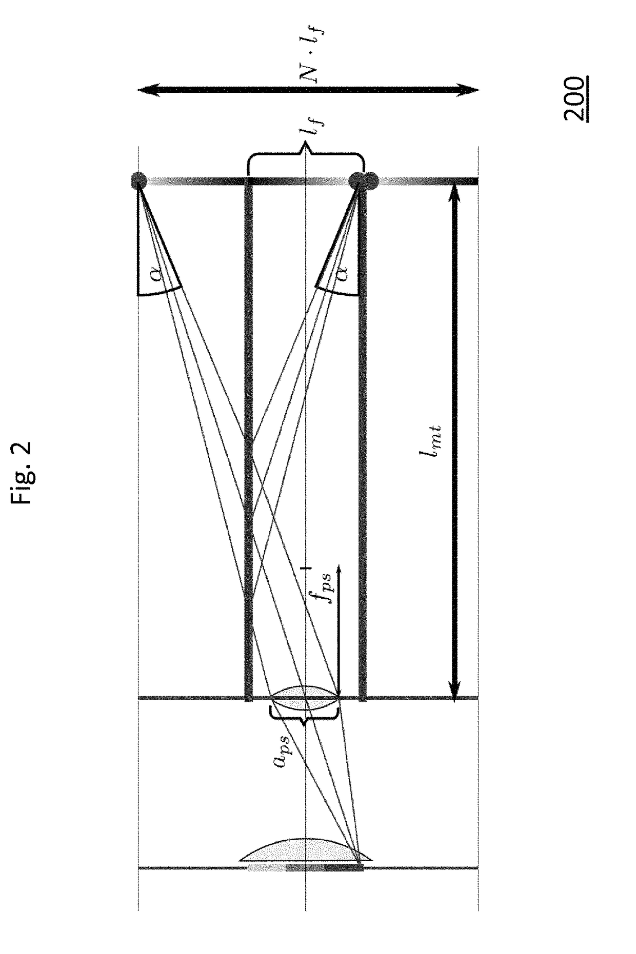
[0052]By omitting the diffuser component, one preserves the directionality of the plenoptic function on the entrance plane and can sample it in the sub-images. A difficulty is the divergent nature of the image cast by the main lens onto the entrance plane, see FIG. 4 (a). For clarity, a pinhole-like aperture of the pickup system is shown, including two scene points that are imaged from three directions each. One sees that vignetting occurs; the blue view is completely blocked for the upper scene point whereas the green view is missing for the lower scene point. The problem comes from the mismatch between the e...


PUM


Abstract

A plenoptic imaging device according to the invention comprises an image multiplier (130) for obtaining a multitude of optical images of an object or scene and a pick-up system (140) for imaging at least some of the multitude of images to a common image sensor (170) during the same exposure of the sensor.

Description

CROSS-REFERENCE TO RELATED APPLICATIONS[0001]This application is a National Stage of International Application No. PCT / EP2014 / 052747, filed Feb. 12, 2014, which claims the benefit of (i) U.S. Provisional Application No. 61 / 764,084, filed Feb. 13, 2013; and (ii) and EP 13155094.9, filed Feb. 13, 2013, the entire contents of both of which are hereby fully incorporated herein by reference for all purposes.[0002]The present invention relates to a non-permanent, reconfigurable camera add-on for high dynamic range, multispectral, polarization, and light-field imaging.TECHNICAL BACKGROUND[0003]Imaging dimensions of the plenoptic function has been a long-standing goal [Adelson and Bergen 1991]. Access to the full properties of the incident light on a sensor, e.g. the direction, spectrum, the temporal variation, the polarization and other properties has a large number of applications in scientific imaging, industrial quality control, remote sensing, computer vision, and computer graphics.[00...

Claims


Application Information

Patent Timeline
Patent Type & Authority Patents(United States)
IPC IPC(8): H04N9/07H04N5/225H04N9/083G02B5/04G02B27/08G02B5/20G02B5/02
CPCH04N13/0257G02B5/04H04N5/2254H04N13/0217H04N2213/001G02B5/201G02B27/08H04N13/0214G02B5/0273H04N13/214H04N13/218H04N13/257G02B27/0075H04N23/55
Inventor KLEHM, OLIVERIHRKE, IVORESTREPO, JOHNMANAKOV, ALKHAZURHEGEDUS, RAMON
Owner KLENS GMBH
Learn More