
Sealing device and method for sealing fractures or leaks in wall or formation surrounding tube-shaped channel

Active Publication Date: 2018-04-10
TOTAL E&P DANMARK AS +1
View PDF13 Cites 0 Cited by
  • Summary
  • Abstract
  • Description
  • Claims
  • Application Information

AI Technical Summary

Benefits of technology

The invention describes a method for sealing a fluid in a tube-shaped channel. The method includes ejecting the sealing fluid from a placement section and displacing it away from the channel, using a second annular flow barrier to remove any excess fluid. This prevents the sealing device from becoming blocked or leaking during curing. The method also includes measuring the pressure of the fluid at different locations in the channel and comparing it to a reference pressure difference. This ensures that the sealing fluid is correctly placed and has adequately penetrated any fractures or leaks. The technical effect is to prevent premature curing of the sealing fluid and improve the accuracy and reliability of the sealing process.

Problems solved by technology

However, in practice, the device must be left in place in the well bore until the sealing fluid has set, as cross flow in the well bore may otherwise wash away the sealing fluid.
When the device is to be removed, the set sealing fluid may render the removal of the device difficult and may prevent subsequent activation of the inflatable packers.
Furthermore, if sealing fluid leaks from the isolated portion of the wellbore between the packers to the remaining part of the wellbore, the sealing fluid will set there and may be difficult to remove again.
Furthermore, in the latter case, the sealing fluid pressure obtained in the section of the wellbore to be treated may have been too low with the result that fractures or leaks to be sealed have not been sufficiently deeply penetrated by sealing fluid before the sealing fluid starts curing.
This may result in a situation wherein said fractures or leaks are insufficiently sealed so that the sealing effect may be too weak.
However, as the entrance of said fractures or leaks is in fact sealed, it may be difficult or even impossible to provide a deeper seal at a subsequent treatment.
However, this method is directed at cementing a well bore in its entire length and is not suitable for the sealing of fractures or leaks in a selected part of a well bore or the like.

Method used


Image

  • Sealing device and method for sealing fractures or leaks in wall or formation surrounding tube-shaped channel
  • Sealing device and method for sealing fractures or leaks in wall or formation surrounding tube-shaped channel
  • Sealing device and method for sealing fractures or leaks in wall or formation surrounding tube-shaped channel

Examples


first embodiment

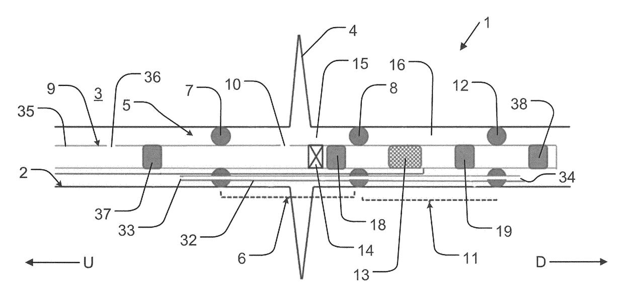
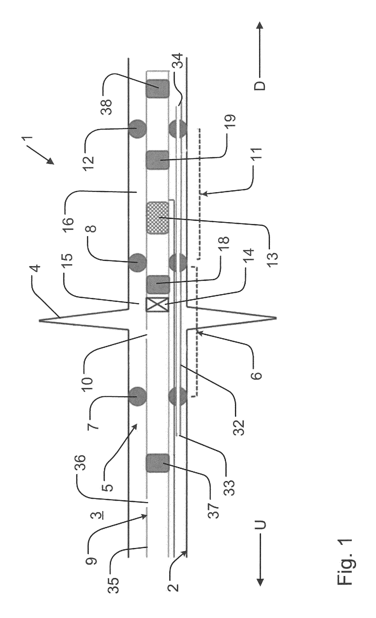
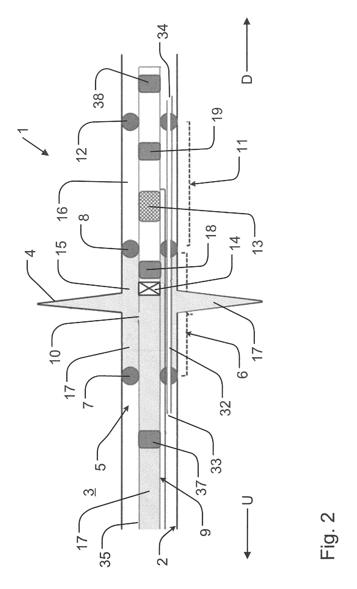
[0098]In a first embodiment, the sealing fluid 17 forms a first component of a two-part epoxy, and an activation fluid forms a second component of said two-part epoxy. The activation fluid may be ejected by the sealing fluid activation section 11 in order to start curing of the epoxy. Furthermore, the sealing fluid activation section 11 may include a heater in order to accelerate curing of a resulting thermosetting polymer.

second embodiment

[0099]In a second embodiment, the sealing fluid 17 may include particles having a protective outer layer or coating enclosing a first component of a two-part epoxy and / or particles having a protective outer layer or coating enclosing a second component of said two-part epoxy. Thereby, said first and second components may be separated during placement of the sealing fluid 17. Removal of the protective layer may take place as described above by means of the sealing fluid activation device 13. Furthermore, the sealing fluid activation section 11 may include a heater in order to accelerate curing of a resulting thermosetting polymer.

[0100]Optionally, the sealing fluid 17 may comprise a filler, for instance in the form of sand, grit, glass fibres, stone fibres or any other suitable material that may strengthen the material.


PUM


Abstract

The sealing device (1) includes an elongated body (5) adapted to be introduced into a tube-shaped channel (2) and including a sealing fluid placement section (6) arranged between a first and a second annular flow barrier (7, 8). The elongated body further includes a sealing fluid activation section (11) arranged between the second annular flow barrier (8) and a third annular flow barrier (12) and including a sealing fluid activation device (13) adapted to at least initiate or accelerate curing of the sealing fluid (17). In operation, the elongated body may be displaced along the tube-shaped channel until the sealing fluid activation section is placed at a position where sealing fluid has been ejected by the sealing fluid placement section, and the sealing fluid activation device may be activated. Thereby, sealing fluid may be cured at selected locations along the tube-shaped channel after ejection of sealing fluid.

Description

RELATED APPLICATIONS[0001]This application claims the benefit under 35 U.S.C. § 371 of International Patent Application No. PCT / EP2013 / 074861, having an international filing date of Nov. 27, 2013, which claims priority to European Application No. 12194965.5, filed Nov. 30, 2012, the contents of all of which are incorporated herein by reference in their entirety.BACKGROUND OF THE INVENTIONField of the Invention[0002]The present invention relates to a sealing device for sealing fractures or leaks in a wall or formation surrounding a tube-shaped channel, such as a drain, pipeline or well bore.Description of Related Art[0003]U.S. Pat. No. 6,955,216 B1 discloses a device for injecting a fluid into an earth formation surrounding a wellbore. For example, such injection is desirable in order to seal-off a formation, or a natural or induced fracture in a formation, around a perforated well tubular in the wellbore. The device is suitable to be arranged in the wellbore and is provided with a p...

Claims


Application Information

Patent Timeline
IPC IPC(8): E21B21/00E21B33/13E21B33/124E21B33/138
CPCE21B33/13E21B33/138E21B33/124E21B21/00
Inventor HANSEN, JENS HENRIKSKOV, ANNE LADEGAARD
Owner TOTAL E&P DANMARK AS
Learn More