Anti-locking mechanism of spherical compressor rotor, Anti-locking power mechanism of spherical compressor, and spherical compressor

Active Publication Date: 2016-11-17
SHENZHEN ZHONGKE ZHENGAN SCI & TECH PARTNERSHIP ENTERPRISE LLP
View PDF6 Cites 0 Cited by
  • Summary
  • Abstract
  • Description
  • Claims
  • Application Information

AI Technical Summary

Benefits of technology

[0027](2) The anti-locking power mechanism of the spherical compressor provided in the present invention can prevent the pressure leakage in the spherical cavity and facilitates the sealing, thereby being applicable to small-sized and micro compressors and high pressure occasions, and increasing the operation efficiency of the compressor;
[0028](3) According to the anti-locking power mechanism of the spherical compressor provided in the present invention, in the structure of the compressor of the same discharge capacity, since the structural size of the slip shoe or the pulley is relatively large, the contact area with the track limiting surface is large, and the carrying capacity is high; the slide friction of the pulley is small, so that the pulley is flexible to move; and the slip shoe is made of the wear-resistant PEEK material or the copper with a self-lubrication function, so that the slide guide effect is good, and the service life is long. Meanwhile, the turntable power synchronizing mechanism is low in machining difficulty and reliable in use;
[0029](4) The anti-locking power mechanism of the spherical compressor provided in the present invention forms the backpressure support on the turntable spherical surface, thereby reducing the

Problems solved by technology

At present, the spherical compressor technology has already achieved multiple patents both in China and abroad; however, when the main shaft rotates to a position at which the turntable axis and the piston axis are superposed, a dead point of movement of the mechanism is generated, thereby easily resulting in locking and incapable rotation of the mechanism; and particularly under the working condition of small structural size, poor lubrication and high pressure ratio, the locking phenomenon is more apparent.
Because the rotation of the piston is driven by an eccentric main shaft, when the main shaft rotates to a position at which the turntable axis and the piston axis are superposed, a resultant force generated by the main shaft on a turntable is perpendicularly intersected with the axes of the pist

Method used


Image

  • Anti-locking mechanism of spherical compressor rotor, Anti-locking power mechanism of spherical compressor, and spherical compressor
  • Anti-locking mechanism of spherical compressor rotor, Anti-locking power mechanism of spherical compressor, and spherical compressor
  • Anti-locking mechanism of spherical compressor rotor, Anti-locking power mechanism of spherical compressor, and spherical compressor

Examples


Example

[0073]The details of the present invention can be understood more clearly in combination with the drawings and the description of the specific embodiments of the present invention. However, the specific embodiments of the present invention described herein are merely used for the purpose of explaining the present invention, rather than understood to limit the present invention by any means. Enlightened by the present invention, those skilled in the art can concept any possible deformations based on the present invention, all of which should be regarded as belonging to the scope of the present invention.

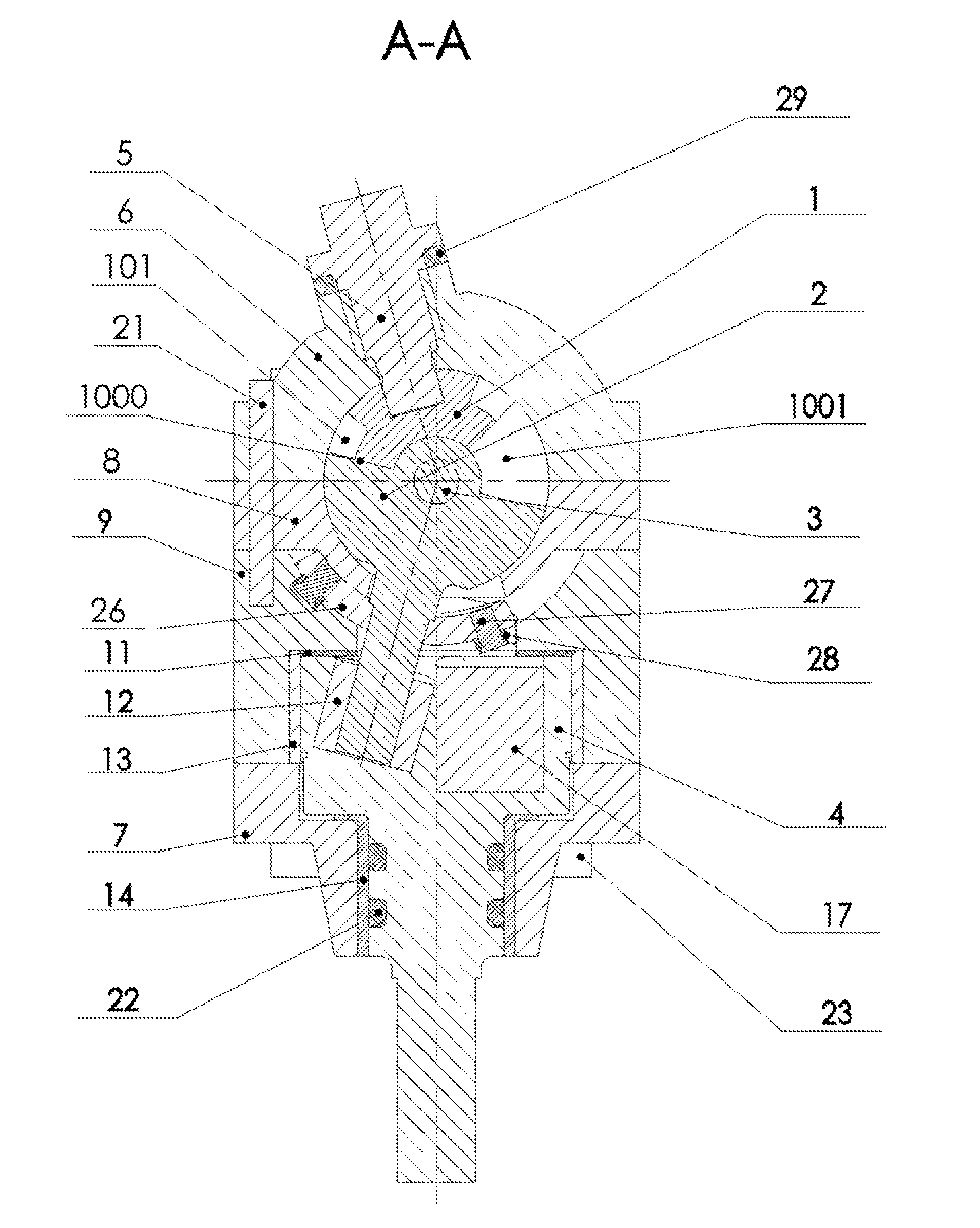
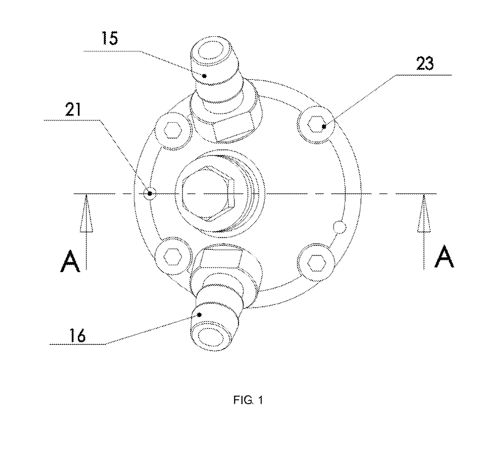
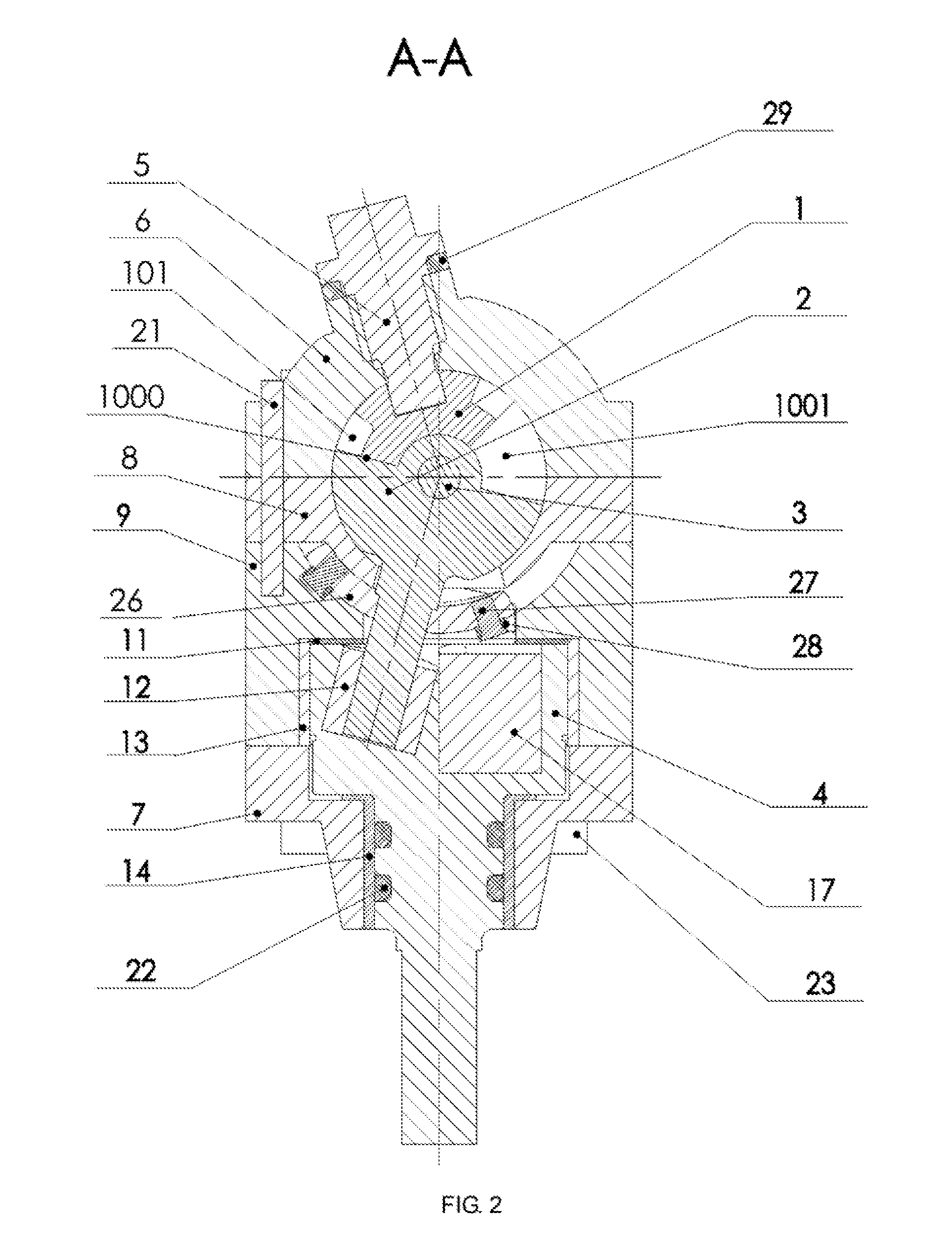
[0074]As shown in FIG. 1 and FIG. 2 or FIG. 16 and FIG. 17, the spherical compressor provided in some embodiments of the present invention comprises: a cylinder head 6, a piston 1, a cylinder 8, a turntable 2, an anti-locking device, a main shaft support 7 and a main shaft 4, wherein as shown in FIG. 5 and FIG. 6 or FIG. 20 and FIG. 21, the cylinder head 6 is a hollow semi-spherical s...


PUM


Abstract

An anti-locking mechanism of a spherical compressor rotor, an anti-locking power mechanism of a spherical compressor, and a spherical compressor. A pin boss is fixedly arranged on a turntable shaft, and guide pins are movably connected with a guide sleeve. A concave slideway is arranged in a cylinder block spherical surface or a cylinder lower spherical surface, and is distributed along a sliding track of the guide sleeve on the corresponding cylinder block spherical surface or cylinder lower spherical surface in a rotation process of a turntable. A main shaft rotates and drives the turntable. When the turntable rotates to a position at which a turntable axis and a piston axis are superposed, the turntable can continue to rotate around the turntable axis by means of torque obtained by the guide pin from the concave slideway, and thus a problem of a dead point of movement of a spherical compressor rotor is solved. Because the concave slideway is arranged outside a spherical working cylinder of a spherical compressor, the sealing effect is good.

Description

CROSS-REFERENCE TO RELATED APPLICATIONS[0001]This application is a continuation of International Patent Application No. PCT / CN2015 / 073501 with a filing date of Mar. 2, 2015, designating the United States, now pending, and further claims priority to Chinese Patent Application No. 201410100390.X with a filing date of Mar. 18, 2014, No. 201410554836.6 with a filing date of Oct. 19, 2014. The content of the aforementioned applications, including any intervening amendments thereto, are incorporated herein by reference.TECHNICAL FIELD[0002]The present invention relates to a spherical compressor, and particularly relates to an anti-locking mechanism of a spherical compressor rotor, an anti-locking power mechanism of a spherical compressor, and a spherical compressor.BACKGROUND OF THE PRESENT INVENTION[0003]The spherical compressor technology is a new subject developed in recent years. The structure and the principle of the spherical compressor are completely different from those of the exi...

Claims


Application Information

Patent Timeline
IPC IPC(8): F04C29/00F04C18/54
CPCF04C29/0057F04C18/54F04C2250/20F04C2240/30F04C2240/20F04C2240/60F04C29/0042
Inventor WANG, LUYI
Owner SHENZHEN ZHONGKE ZHENGAN SCI & TECH PARTNERSHIP ENTERPRISE LLP
Why Eureka
Try Eureka