
Sealing mechanism for subsea capping system

Active Publication Date: 2015-06-30
ONESUBSEA IP UK LTD
View PDF18 Cites 0 Cited by
  • Summary
  • Abstract
  • Description
  • Claims
  • Application Information

AI Technical Summary

Benefits of technology

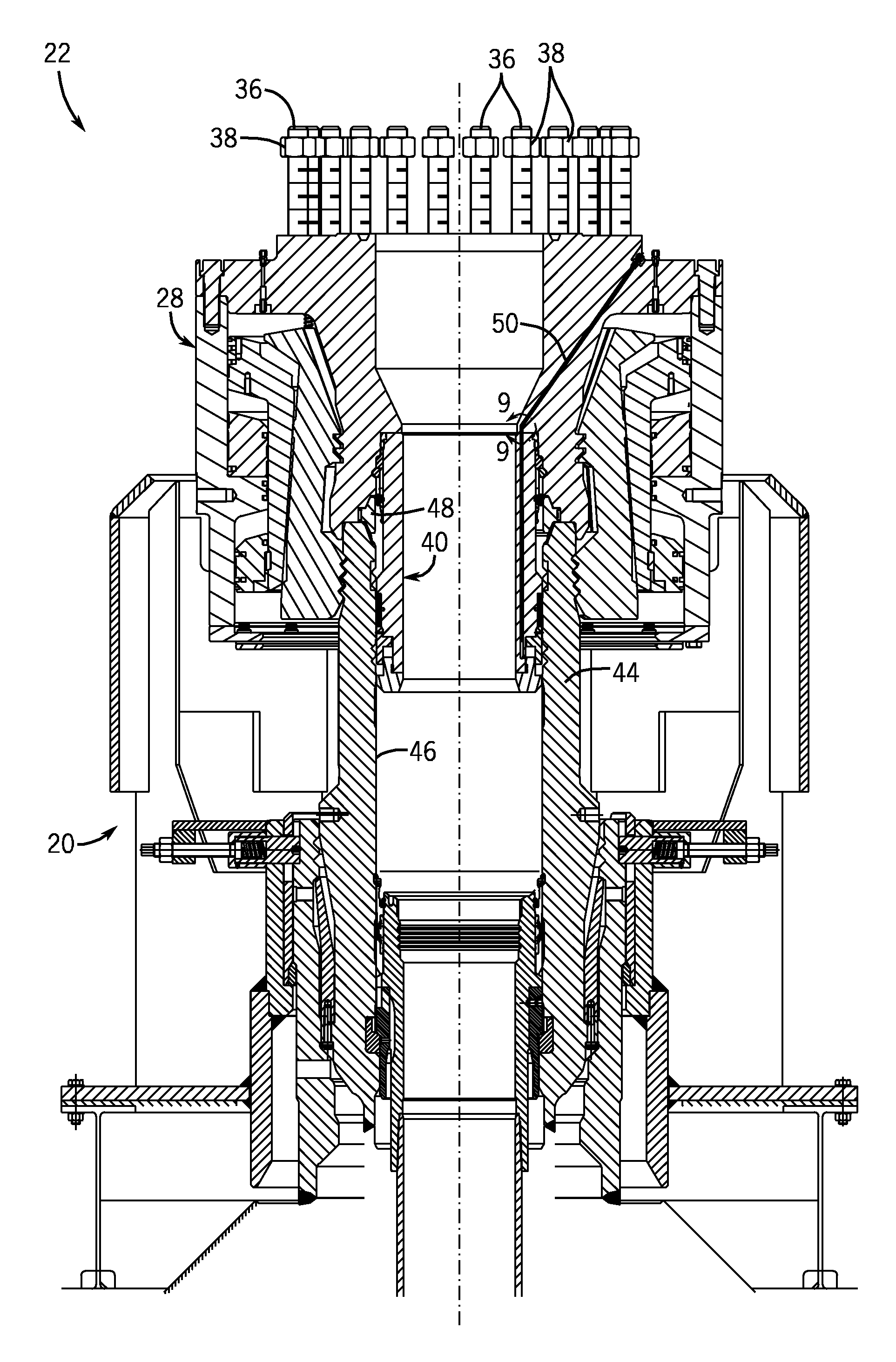
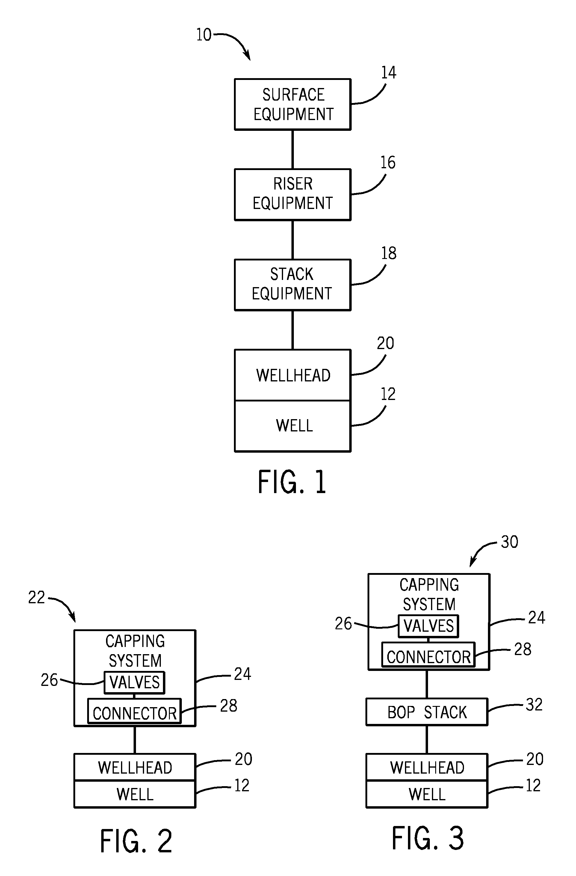
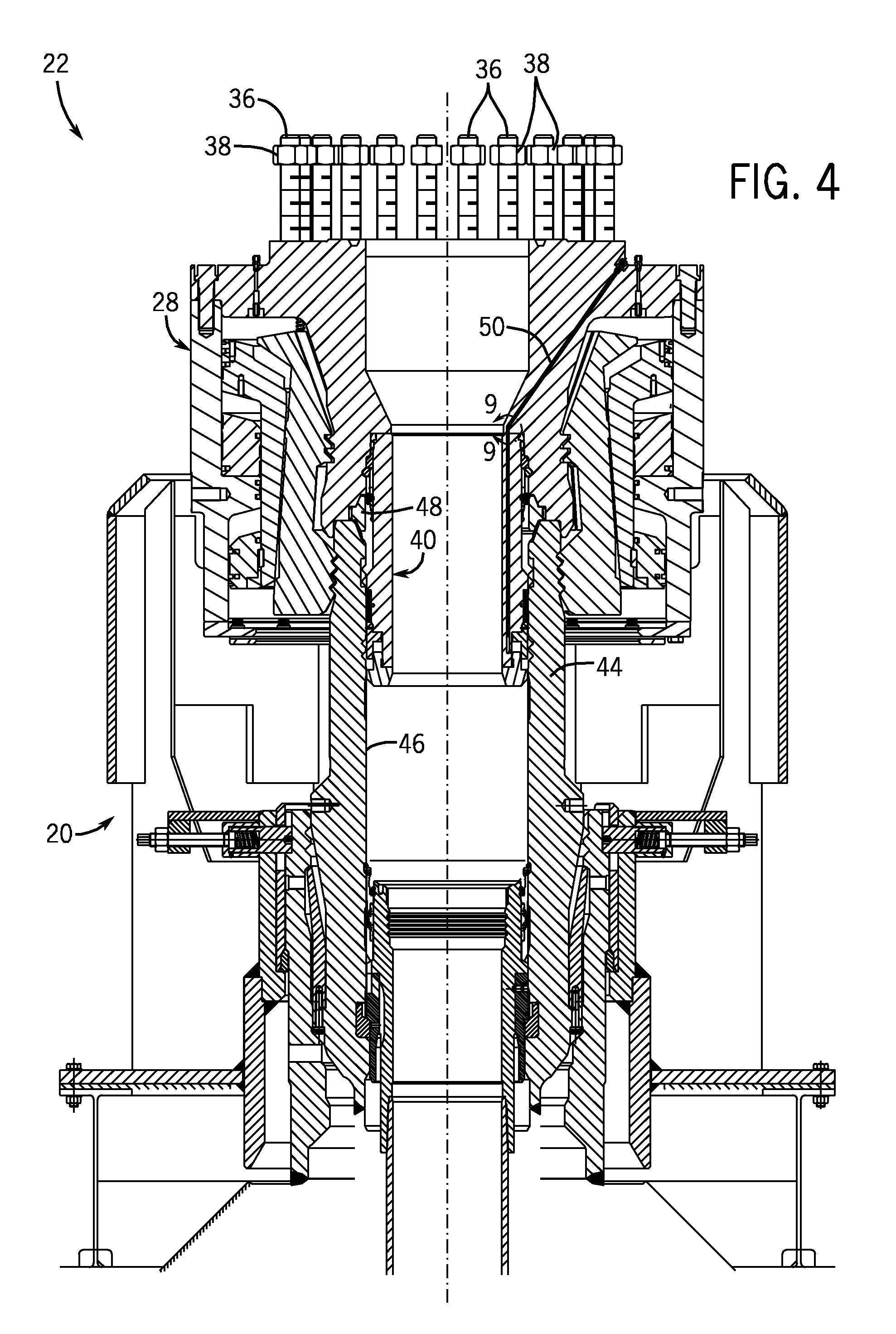
The present patent relates to a sealing mechanism for joining two components together. The mechanism includes an isolation sleeve with a hydraulically actuated piston to create a seal. The isolation sleeve is often used in a connector of a capping system and can be landed into a wellhead housing or a blowout preventer stack. It is designed to seal against equipment of the wellhead assembly in the event of a blowout, especially if the primary sealing area has been damaged. Overall, the sealing mechanism provides an effective and reliable way to connect components in a wellhead assembly.

Problems solved by technology

And in at least one embodiment, the isolation sleeve may enable the capping system to seal against equipment of the wellhead assembly (e.g., the wellhead housing or the blowout preventer stack) during a blowout condition, particularly if a primary gasket sealing area of the equipment for creating a seal with other components (e.g., the connector of the capping system) has been damaged.

Method used


Image

  • Sealing mechanism for subsea capping system
  • Sealing mechanism for subsea capping system
  • Sealing mechanism for subsea capping system

Examples


Embodiment Construction

[0017]One or more specific embodiments of the present disclosure will be described below. In an effort to provide a concise description of these embodiments, all features of an actual implementation may not be described in the specification. It should be appreciated that in the development of any such actual implementation, as in any engineering or design project, numerous implementation-specific decisions must be made to achieve the developers' specific goals, such as compliance with system-related and business-related constraints, which may vary from one implementation to another. Moreover, it should be appreciated that such a development effort might be complex and time consuming, but would nevertheless be a routine undertaking of design, fabrication, and manufacture for those of ordinary skill having the benefit of this disclosure.

[0018]When introducing elements of various embodiments, the articles “a,”“an,”“the,” and “said” are intended to mean that there are one or more of the...


PUM


Abstract

A sealing mechanism is provided. In one embodiment, a system includes a connector configured to couple one or more flow-control valves to equipment installed at a well and an isolation sleeve configured to be retained by the connector. The isolation sleeve may include a seal and a hydraulically actuated piston disposed adjacent one another about a body of the isolation sleeve such that actuation of the piston engages the seal. Additional systems, devices, and methods are also disclosed.

Description

BACKGROUND[0001]This section is intended to introduce the reader to various aspects of art that may be related to various aspects of the presently described embodiments. This discussion is believed to be helpful in providing the reader with background information to facilitate a better understanding of the various aspects of the present embodiments. Accordingly, it should be understood that these statements are to be read in this light, and not as admissions of prior art.[0002]In order to meet consumer and industrial demand for natural resources, companies often invest significant amounts of time and money in searching for and extracting oil, natural gas, and other subterranean resources from the earth. Particularly, once a desired subterranean resource is discovered, drilling and production systems are often employed to access and extract the resource. These systems may be located onshore or offshore depending on the location of a desired resource. Further, such systems generally i...

Claims


Application Information

Patent Timeline
IPC IPC(8): E21B33/035E21B33/038E21B33/037
CPCE21B33/037E21B33/035E21B33/038E21B33/043
Inventor HART, BRIANBERRY, CAMERON J.
Owner ONESUBSEA IP UK LTD
Learn More