
Pneumatic tire

a technology of pneumatic tires and treads, which is applied in the field of pneumatic tires, can solve the problems of pneumatic tires, uneven and the need to suppress uneven wear, so as to reduce the amount of deformation in the shoulder region of the tread portion when the tire contacts the ground, even wear of the shoulder land portion 3 is effectively suppressed, and the effect of uneven wear

Active Publication Date: 2018-04-24
THE YOKOHAMA RUBBER CO LTD
View PDF67 Cites 0 Cited by
  • Summary
  • Abstract
  • Description
  • Claims
  • Application Information

AI Technical Summary

Benefits of technology

[0004]The present technology provides a pneumatic tire with improved uneven wear resistance performance.
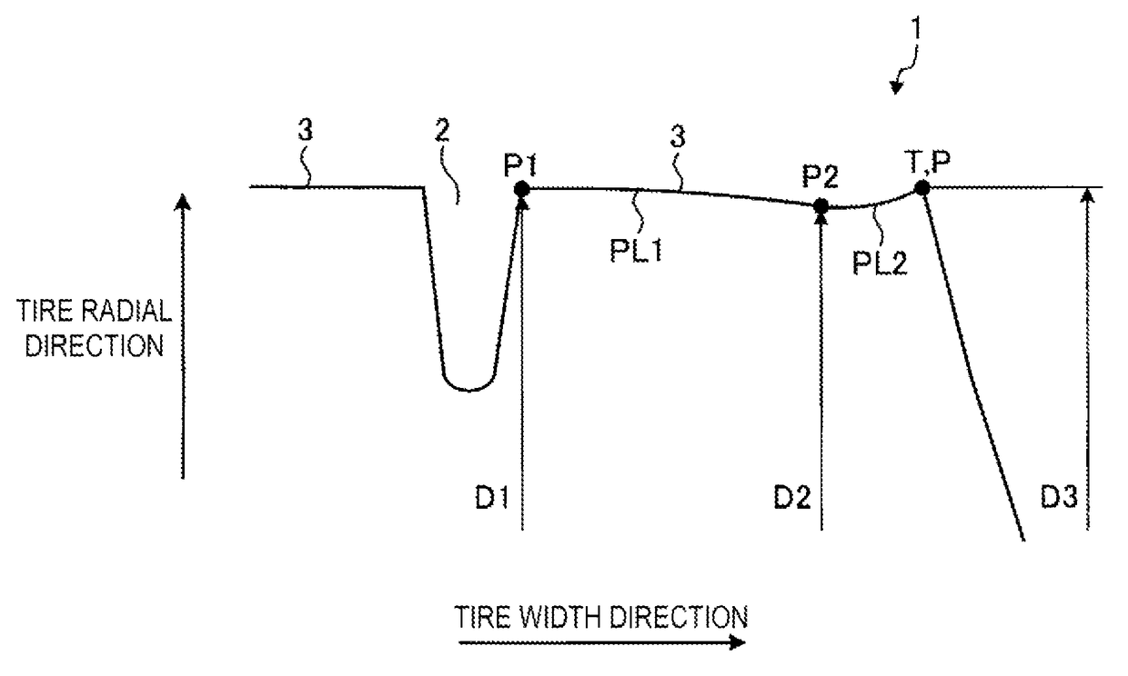
[0006]In the pneumatic tire according to the present technology, a profile of the shoulder land portion in a ground contact region includes a small-diameter portion (a point having a diameter D2 such that D2<D1 and D2<D3) between an edge portion on the inner side in the tire width direction and the tire ground contact edge T. According to this configuration, the ground contact pressure on the side of the ground contact edge T of the shoulder land portion when the tire contacts the ground is increased. Also, the amount of slippage at a center region of the land portion 3 and the amount of slippage of the shoulder land portion when the tire contacts the ground are averaged. As a result, this has the advantage in that the uneven wear of the shoulder land portion 3 is effectively suppressed.

Problems solved by technology

A pneumatic tire has a problem in that uneven wear of a shoulder land portion needs to be suppressed.

Method used


Image

  • Pneumatic tire
  • Pneumatic tire
  • Pneumatic tire

Examples


examples

[0148]FIGS. 9A to 12B are tables showing results of performance testing of pneumatic tires according to embodiments of the present technology.

[0149]In the performance testing, a plurality of pneumatic tires that differ from each other were evaluated as belt-edge-separation resistance performance (see FIGS. 9A to 12B). In the evaluation, pneumatic tires having a tire size of 315 / 60 R22.5 were mounted on a rim having a rim size of 22.5×9.00 and inflated with 900 kPa of air pressure. In addition, the pneumatic tires were mounted on the front axle of a testing vehicle that is a 4×2 tractor trailer, and a load of 34.81 kN was applied. Then, after driving the testing vehicle for 100,000 km, the amount of shoulder-dropping wear on the shoulder land portion (difference between the amount of wear on the edge portion of the shoulder land portion and the amount of wear on the outermost circumferential main groove) was measured and evaluated. A larger numerical value is preferable in the evalua...


PUM

PropertyMeasurementUnit
belt angleaaaaaaaaaa

Abstract

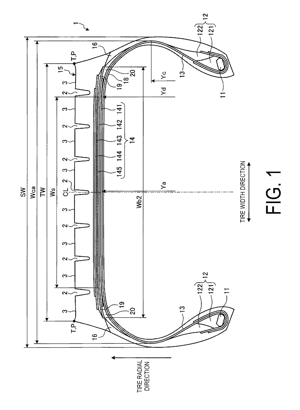
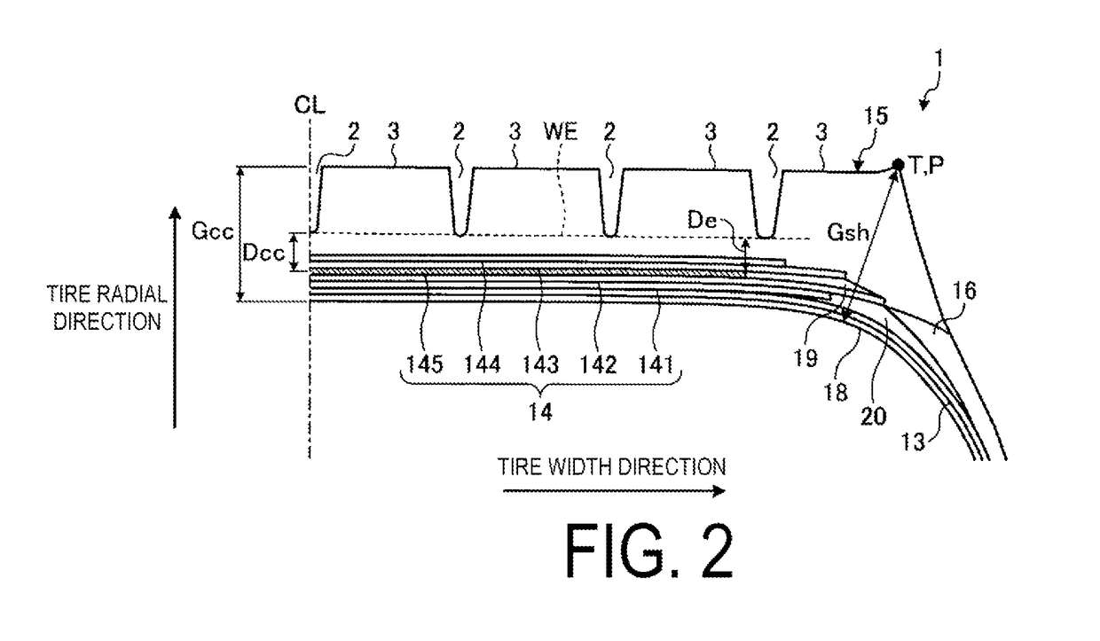
A pneumatic tire includes at least three circumferential main grooves that extend in the tire circumferential direction, and land portions that are partitioned and formed by these circumferential main grooves. In addition, a belt layer is formed by laminating a pair of cross belts each having a belt angle of not less than 10° and not more than 45° as an absolute value and having mutually opposite signs, and a circumferential reinforcing layer having a belt angle within a range of ±5° with respect to the tire circumferential direction. In addition, in a cross-sectional view taken along the tire meridian direction, a diameter D1 at a point at an edge portion on the inner side of a shoulder land portion in the tire width direction and a diameter D2 at a predetermined point within the ground-contact surface of the shoulder land portion have a relationship such that D2<D1.

Description

TECHNICAL FIELD[0001]The present technology relates to a pneumatic tire, and particularly relates to a pneumatic tire with improved uneven wear resistance performance.BACKGROUND ART[0002]In recent years, heavy duty tires mounted on trucks, buses, and the like maintain the shape of the tread portion due to the tires having a low aspect ratio while having a circumferential reinforcing layer disposed in a belt layer. The circumferential reinforcing layer is a belt ply having a belt angle that is substantially 0° with respect to the tire circumferential direction, and is disposed so as to be stacked upon a pair of cross belts. The technologies disclosed in Japanese Patent Nos. 4642760B, 4663638B and 4663639B, as well as in Japanese Unexamined Patent Application Publication No. 2012-522686 are conventional pneumatic tires that are configured in this manner.[0003]A pneumatic tire has a problem in that uneven wear of a shoulder land portion needs to be suppressed.SUMMARY[0004]The present t...

Claims


Application Information

Patent Timeline
Patent Type & Authority Patents(United States)
IPC IPC(8): B60C11/01B60C9/18B60C5/00B60C9/00B60C9/04B60C9/20B60C9/28B60C11/00
CPCB60C9/18B60C5/00B60C9/0007B60C9/04B60C9/28B60C11/01B60C9/2006B60C2200/06B60C2011/0033B60C2011/013
Inventor KOTOKU, KOICHI
Owner THE YOKOHAMA RUBBER CO LTD
Learn More