
Tyre for a motorcycle

a technology for motorcycles and tyres, applied in motorcycle tyres, vehicle components, vehicle parts, etc., can solve problems such as uneven wear, and achieve the effect of improving uneven wear resistance performan

Active Publication Date: 2020-06-18
SUMITOMO RUBBER IND LTD
View PDF4 Cites 1 Cited by
  • Summary
  • Abstract
  • Description
  • Claims
  • Application Information

AI Technical Summary

Benefits of technology

The invention provides a motorcycle tire that can improve its resistance to uneven wear and tear.

Problems solved by technology

In the peripheral regions of the convex portions described above, in the tyre circumferential direction and in a tyre axial direction, portions where the grooves are formed and portions where the grooves are not formed alternately come into contact with the ground during running, therefore, it is possible that uneven wear is generated.

Method used


Image

  • Tyre for a motorcycle
  • Tyre for a motorcycle
  • Tyre for a motorcycle

Examples


working examples (examples)

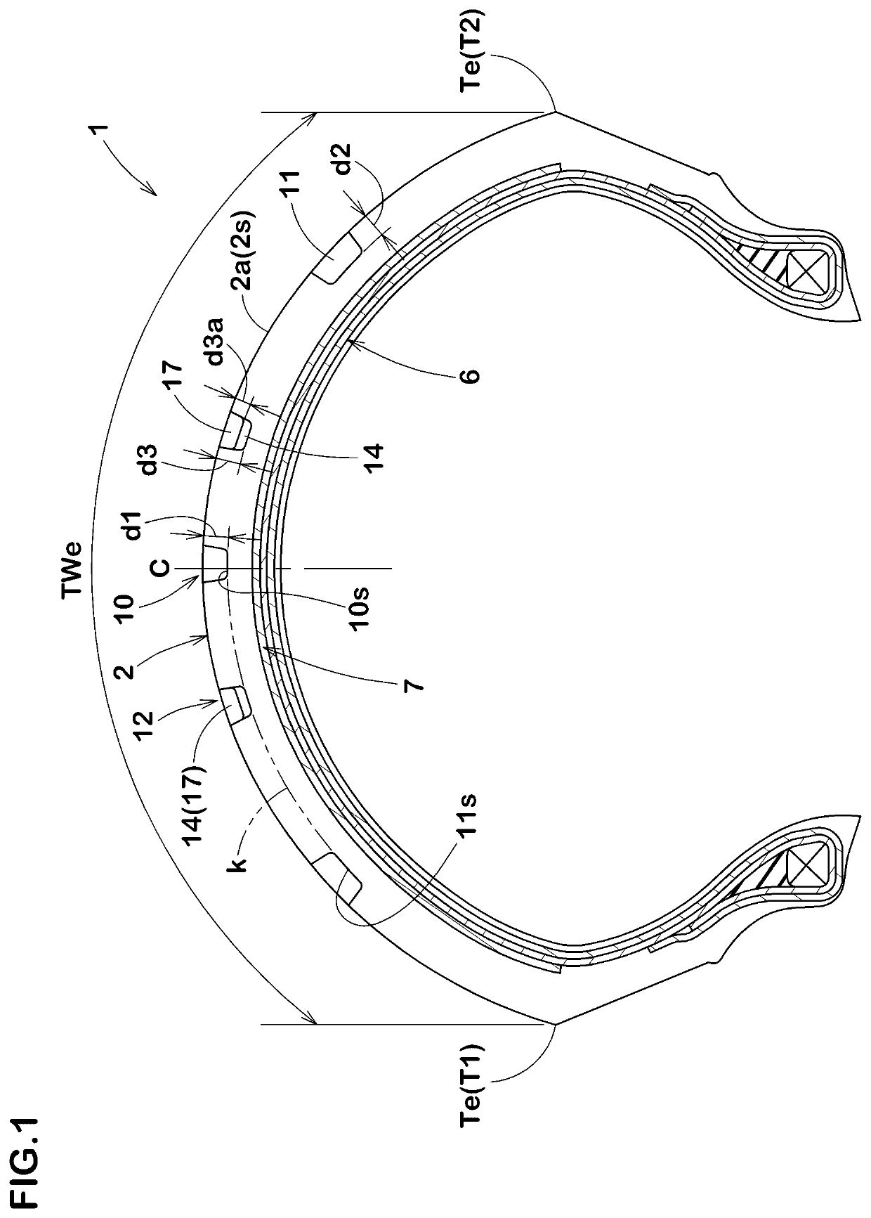
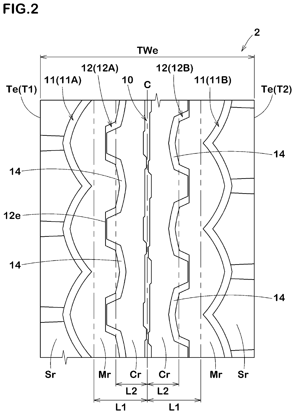
[0077]Tyres for a motorcycle having the basic pattern shown in FIG. 1 were made by way of test according to the specifications listed in Table 1, and then each of the test tyres was tested for the uneven wear resistance performance. Common specifications of the test tyres and the test method were as follows.

[0078]Depth of each of Crown longitudinal groove, shoulder longitudinal groove, and virtual line: 4.0 mm

[0079]Groove depth of shallow bottom portion: 3.2 mm

[0080]Each of the test tyres were mounted on a test vehicle described below and a test rider drove the test vehicle on a dry asphalt road surface of a test course for a distance of 5000 km, and then the generation of the uneven wear after the test run was observed. The uneven wear resistance performance was evaluated by the driver's feeling and the test results are indicated by an evaluation point on a scale of 1 to 5, wherein a larger numerical value is better.

[0081]Tyre: 120 / 70ZR17 (front wheel), 180 / 55ZR17 (rear wheel)

[0082...


PUM


Abstract

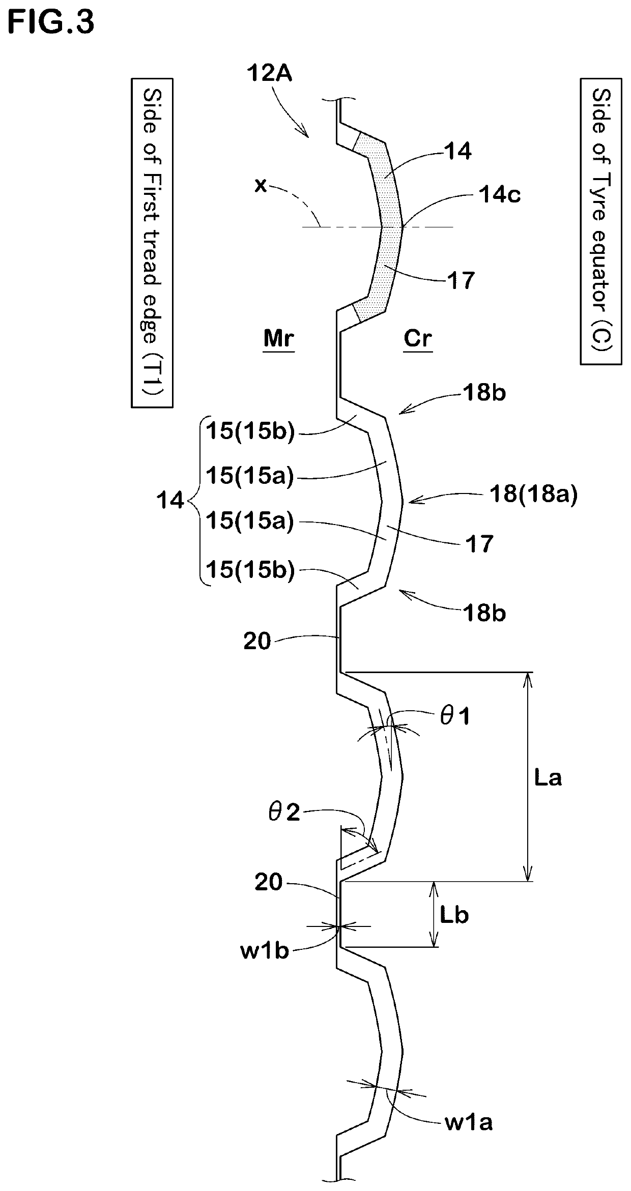
A tyre for a motorcycle includes a tread portion. The tread portion includes a crown longitudinal groove extending in a tyre circumferential direction on a side of a tyre equator, a shoulder longitudinal groove extending in the tyre circumferential direction on a side of a first tread edge, and a middle groove arranged between the crown longitudinal groove and the shoulder longitudinal groove. The middle groove includes a plurality of middle main groove portions arranged in the tyre circumferential direction and each protruding toward the tyre equator or the first tread edge. Each of the middle main groove portions is formed in a bent line shape or in an arc shape. Each of the middle main groove portions includes a shallow bottom portion having a groove depth smaller than a maximum groove depth of the shoulder longitudinal groove and a maximum groove depth of the crown longitudinal groove.

Description

TECHNICAL FIELD[0001]The present invention relates to a tyre for a motorcycle.BACKGROUND ART[0002]Japanese Unexamined Patent Application Publication No. S59-227510 describes a tyre for a motorcycle provided in a tread with grooves extending in a tyre circumferential direction. The grooves include a groove arranged in a crown portion, a pair of grooves each arranged on a side of a respective one of tread edges, a pair of grooves each arranged between the crown portion and a respective one of the tread edges. Each of the grooves arranged between the crown portion and a respective one of the tread edges is formed by portions each convex toward a side of the crown portion and portions each convex toward a side of a respective one of the tread edges arranged alternately in the tyre circumferential direction.SUMMARY OF THE INVENTION[0003]In the peripheral regions of the convex portions described above, in the tyre circumferential direction and in a tyre axial direction, portions where the...

Claims


Application Information

Patent Timeline
Patent Type & Authority Applications(United States)
IPC IPC(8): B60C11/03
CPCB60C2011/0358B60C11/03B60C2011/0355B60C11/1236B60C2011/0341B60C2200/10B60C11/04B60C2011/0351B60C2011/0353B60C11/032B60C2011/0346B60C11/1369B60C11/0306B60C2011/0344
Inventor OTANI, MASAFUMI
Owner SUMITOMO RUBBER IND LTD
Learn More