Display device for vehicles

Active Publication Date: 2018-06-05
JET OPTOELECTRONICS CO LTD
View PDF10 Cites 2 Cited by
  • Summary
  • Abstract
  • Description
  • Claims
  • Application Information

AI Technical Summary

Benefits of technology

[0016]The display device for vehicles according to the present disclosure can be mounted at any suitable location on an inside roof of a vehicle

Problems solved by technology

However, the base of conventional display devices is quite large and occupies lots of space.
Besides, most conventional screens and bases are fixedly connect

Method used


Image

  • Display device for vehicles
  • Display device for vehicles
  • Display device for vehicles

Examples


Example

[0029]Reference will now be made in detail to the exemplary embodiments of the present disclosure, examples of which are illustrated in the accompanying drawings. Wherever possible, the same reference numbers are used in the drawings and the description to refer to the same or like parts.

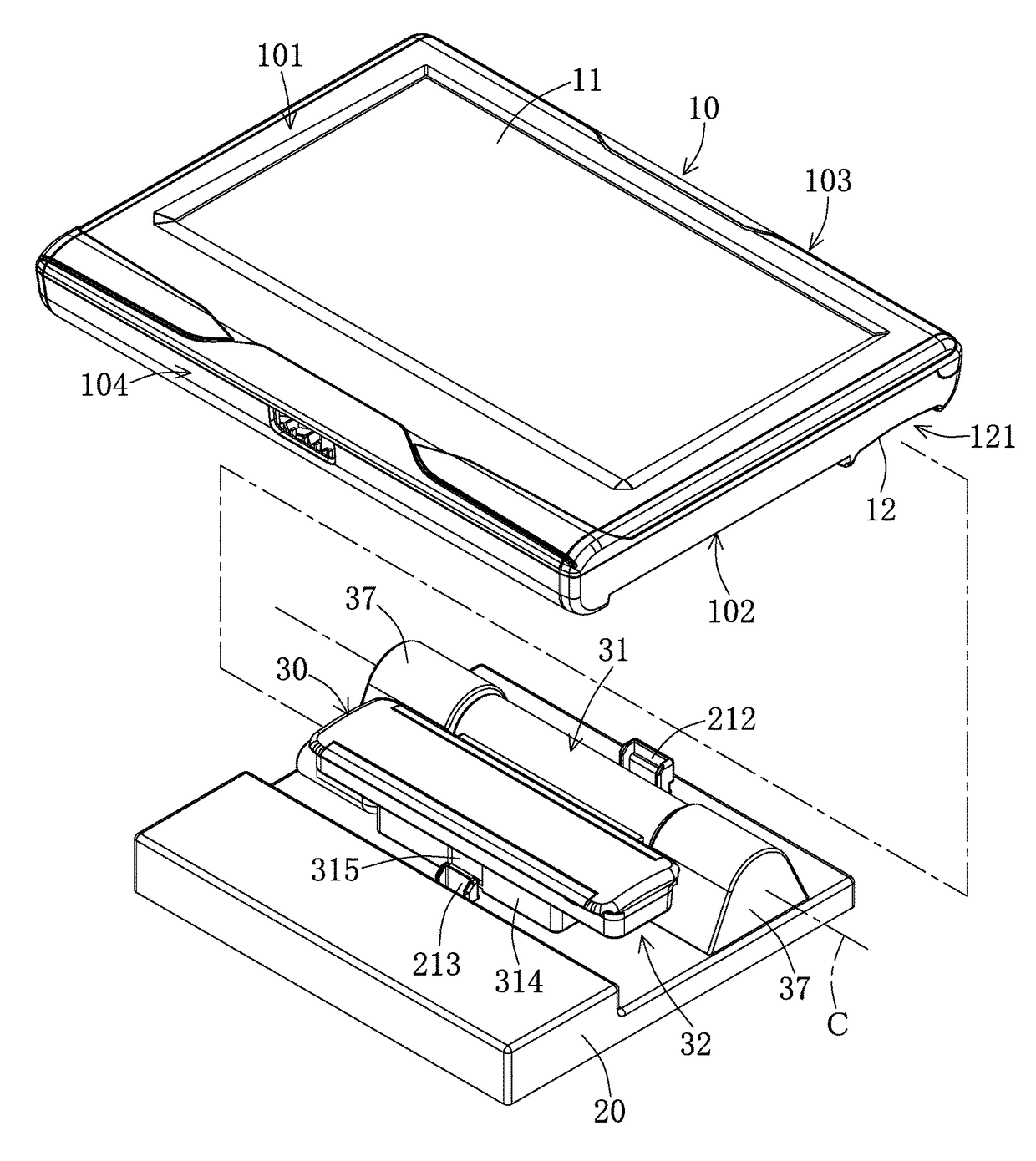
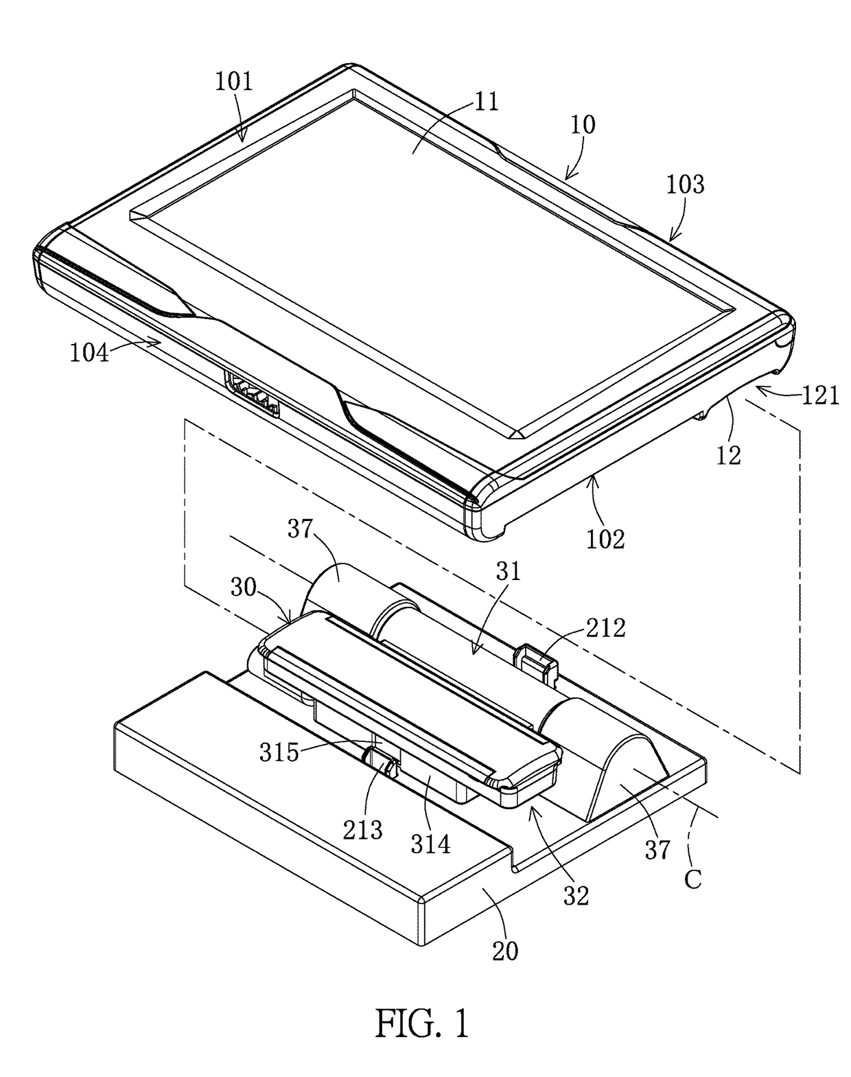
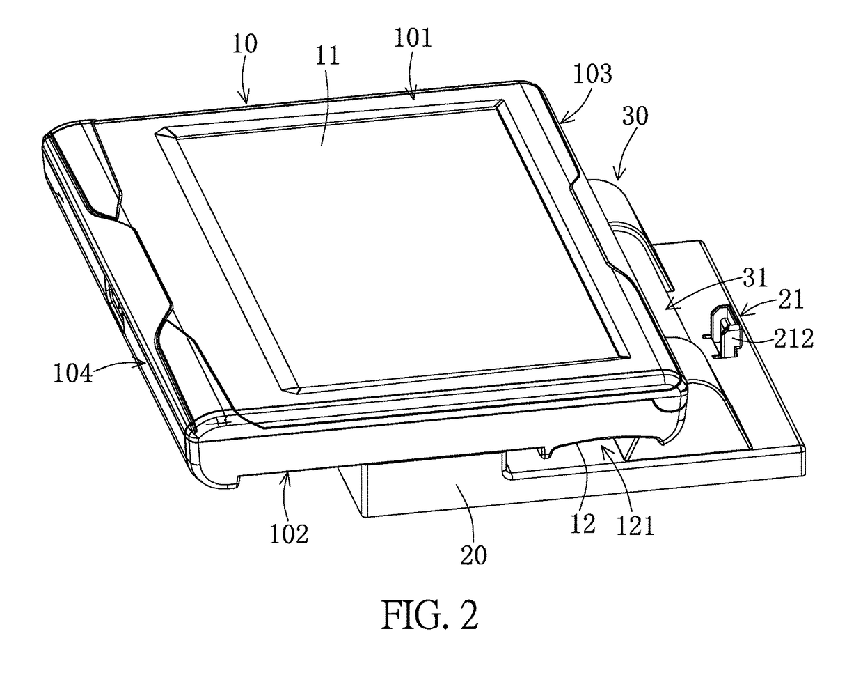
[0030]Referring to FIG. 1 and FIG. 2, the display device of the present disclosure includes a display module 10, a base 20 and a connecting module 30 disposed on the base 20. The base 20 is disposed on the inside roof P of a vehicle (as shown in FIG. 10 to FIG. 12), the connecting module 30 is disposed on the base 20 and includes a hinge 31 and a connecting assembly 32 connected to the hinge 31. The display module 10 is detachably connected to the connecting assembly 32 and is rotatable by the hinge 31 when mounted on the base 20.

[0031]As shown in FIGS. 1, 2 and 6, the display module 10 has a front side 101 and a back side 102 opposite to the front side 101, and a connecting groove 12 is disposed at...


PUM


Abstract

A display device for vehicles is provided. The display device includes: a base, a connecting assembly and a display module. The connecting assembly is disposed on the base by a hinge. The hinge has a pivot of which the center is defined as a central axis. A connecting groove is disposed on the back side of the display module, such that the display module can be connected to the base when the connecting assembly is slidingly inserted into the connecting groove. The connecting assembly can slide in the opposite direction to be removed from the connecting groove of the display module.

Description

BACKGROUND1. Technical Field[0001]The present disclosure is related to a display device for vehicles, and in particular, to a display device that is adapted to be mounted to a vehicle roof.2. Description of Related Art[0002]The structure of conventional car roof display devices are generally designed such that a screen is mounted to a base and fixed to an inside surface of the car roof. However, the base of conventional display devices is quite large and occupies lots of space. Besides, most conventional screens and bases are fixedly connected together by connecting structures, such that the screen cannot be detached from the base, which causes inconvenience for upgrading or changing of screens.[0003]Therefore, there is still room for improvement in the design of the conventional car roof display devices.SUMMARY[0004]The object of the present disclosure is to provide a display device for mounting at an inside roof of a vehicle. The display device according to the present disclosure ...

Claims


Application Information

Patent Timeline
IPC IPC(8): G06F1/16B60K35/00H05K5/00H05K5/02
CPCB60K35/00H05K5/0226H05K5/0204H05K5/0017B60K2350/106B60K2350/922B60R11/0235B60R2011/0028B60R2011/0085B60K2370/816B60K2370/152B60K2370/771
Inventor HUANG, TERRY HSIAO-YANGWEN, TAI-HAO
Owner JET OPTOELECTRONICS CO LTD
Why Eureka
Try Eureka