Complex marking determining device and complex marking determining method

a technology of complex markings and determining devices, which is applied in the direction of image enhancement, instruments, transportation and packaging, etc., can solve the problems of inability to determine, difficulty in accurately identifying the number of potential points, and decrease in detection accuracy of potential lane points

Active Publication Date: 2018-06-05
TOYOTA JIDOSHA KK +1
View PDF36 Cites 1 Cited by
  • Summary
  • Abstract
  • Description
  • Claims
  • Application Information

AI Technical Summary

Benefits of technology

[0013]According to this aspect, the lane marking representative value and the road surface representative value are able to be calculated by a simple calculation process, by calculating the median value of the brightness values of the plurality of pixels that make up the lane marking display region as the lane marking representative value, and calculating the median value of the brightness values of the plurality of pixels that make up the road surface display region as the road surface representative value. Therefore, the complex marking determination is able to be performed quickly.
[0015]According to this aspect, the lane marking representative value and the road surface representative value are able to be calculated by a simple calculation process, by calculating the average value of the brightness values of the plurality of pixels that make up the lane marking display region as the lane marking representative value, and calculating the average value of the brightness values of the plurality of pixels that make up the road surface display region as the road surface representative value. Therefore, the complex marking determination is able to be performed quickly.

Problems solved by technology

With the determination technology described above, in a situation in which the resolution of a camera capturing the image is low, such as with a distant area of the traveling road or the like, the detection accuracy of the potential lane points decreases, which makes it difficult to accurately identify the number of potential points.
Therefore, there may be cases in which it is not possible to determine whether a lane marking of a lane is a complex marking or a single marking.

Method used


Image

  • Complex marking determining device and complex marking determining method
  • Complex marking determining device and complex marking determining method
  • Complex marking determining device and complex marking determining method

Examples


Embodiment Construction

[0032]Hereinafter, example embodiments of the invention will be described with reference to the accompanying drawings. In the drawings, like elements will be denoted by like reference characters, and redundant descriptions will be omitted.

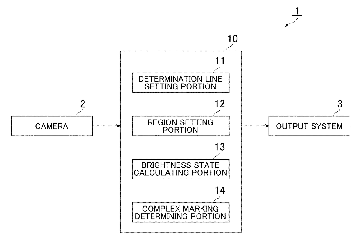
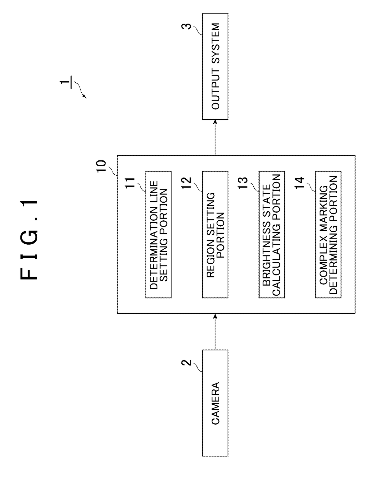
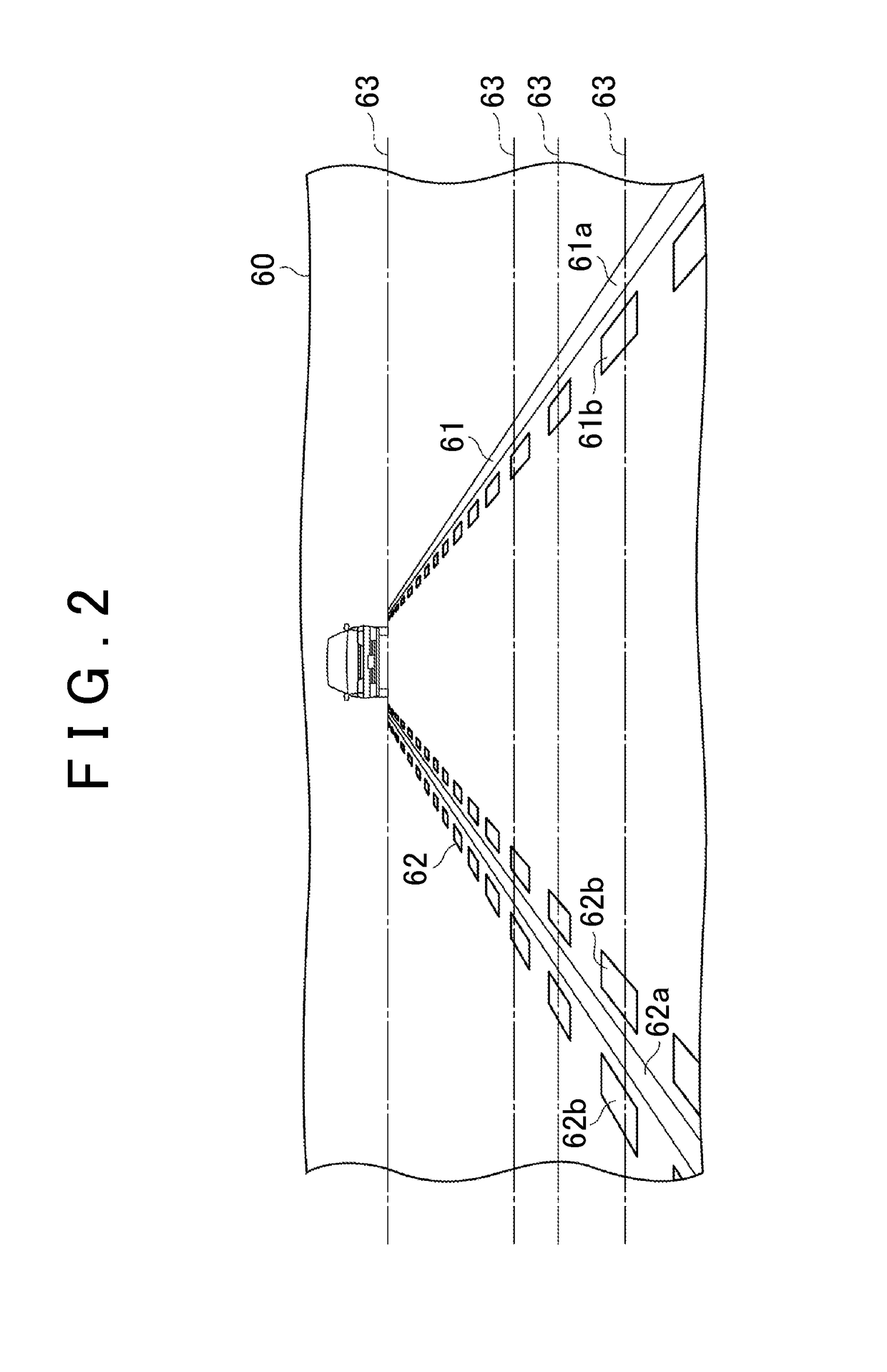
[0033]FIG. 1 is a general diagram of the structure of a complex marking determining device 1 according to a first example embodiment of the invention. FIG. 2 is an explanatory view of a traveling road image used for the complex marking determination by the complex marking determining device 1.

[0034]As shown in FIG. 1, the complex marking determining device 1 is a device that determines whether a lane marking of a traveling lane of a vehicle is a complex marking using a traveling road image captured by a camera 2 mounted on the vehicle. A lane marking of the traveling road is a marking (i.e., a line) that is marked on a road surface of the traveling road and divides lanes, and is referred to as a white line or a lane marker. The lane marking include...


PUM


Abstract

A complex marking determining device includes a brightness state calculating portion configured to calculate a lane marking representative value indicative of a brightness state of a plurality of pixels that make up a lane marking display region, and calculate a road surface representative value indicative of a brightness state of a plurality of pixels that make up the road surface display region; and a complex marking determining portion configured to determine that the lane marking is a complex marking at least when a degree of deviation between the lane marking representative value and the road surface representative value is equal to or greater than a first threshold value.

Description

INCORPORATION BY REFERENCE[0001]The disclosure of Japanese Patent Application No. 2015-006155 filed on Jan. 15, 2015 including the specification, drawings and abstract is incorporated herein by reference in its entirety.BACKGROUND OF THE INVENTION[0002]1. Field of the Invention[0003]The invention relates to a complex marking determining device and a complex marking determining method that determines whether a lane marking of a road on which a vehicle is traveling is a complex marking.[0004]2. Description of Related Art[0005]As technology for determining whether a lane marking of a road on which a vehicle is traveling is a complex marking, technology is known that determines the type of boundary marking of a road on which a vehicle is traveling (hereinafter, also referred to simply as “traveling road”) based on an image of the traveling road, as described in Japanese Patent Application Publication No. 2005-141487 (JP 2005-141487 A). This determination technology attempts to reliably ...

Claims


Application Information

Patent Timeline
Patent Type & Authority Patents(United States)
IPC IPC(8): G06T7/73G06K9/00B60R1/00G06K9/52G06T7/13G06K9/46G06K9/62
CPCG06K9/00798B60R1/00G06K9/4604G06K9/4661G06K9/6215G06T7/13G06T7/73G06K9/52G06T2207/30256G06K2009/4666G06V20/588G06V2201/09G06F18/22
Inventor KATAOKA, YUSUKEKAWASAKI, NAOKISAKAI, TADASHIWATANABE, AKIHIRO
Owner TOYOTA JIDOSHA KK
Why Eureka
Try Eureka