Chuck for meat encasing machines

a technology of meat encasing machine and chuck, which is applied in the directions of sausage twisting/linking machine, application, butchering, etc., can solve problems such as casing ruptur

Inactive Publication Date: 2002-10-15
STORK TOWNSEND BV
View PDF5 Cites 11 Cited by
  • Summary
  • Abstract
  • Description
  • Claims
  • Application Information

AI Technical Summary

Problems solved by technology

However, sometimes the tolerances of these two components are such that the chuck is not firmly grasped by the sleeve and some oscillating movement of the chuck results as it is being rapidly rotated by the sleeve.
This oscillation results in the casing rupturing as the meat emulsion is being extruded therein.

Method used


Image

  • Chuck for meat encasing machines
  • Chuck for meat encasing machines
  • Chuck for meat encasing machines

Examples


Embodiment Construction

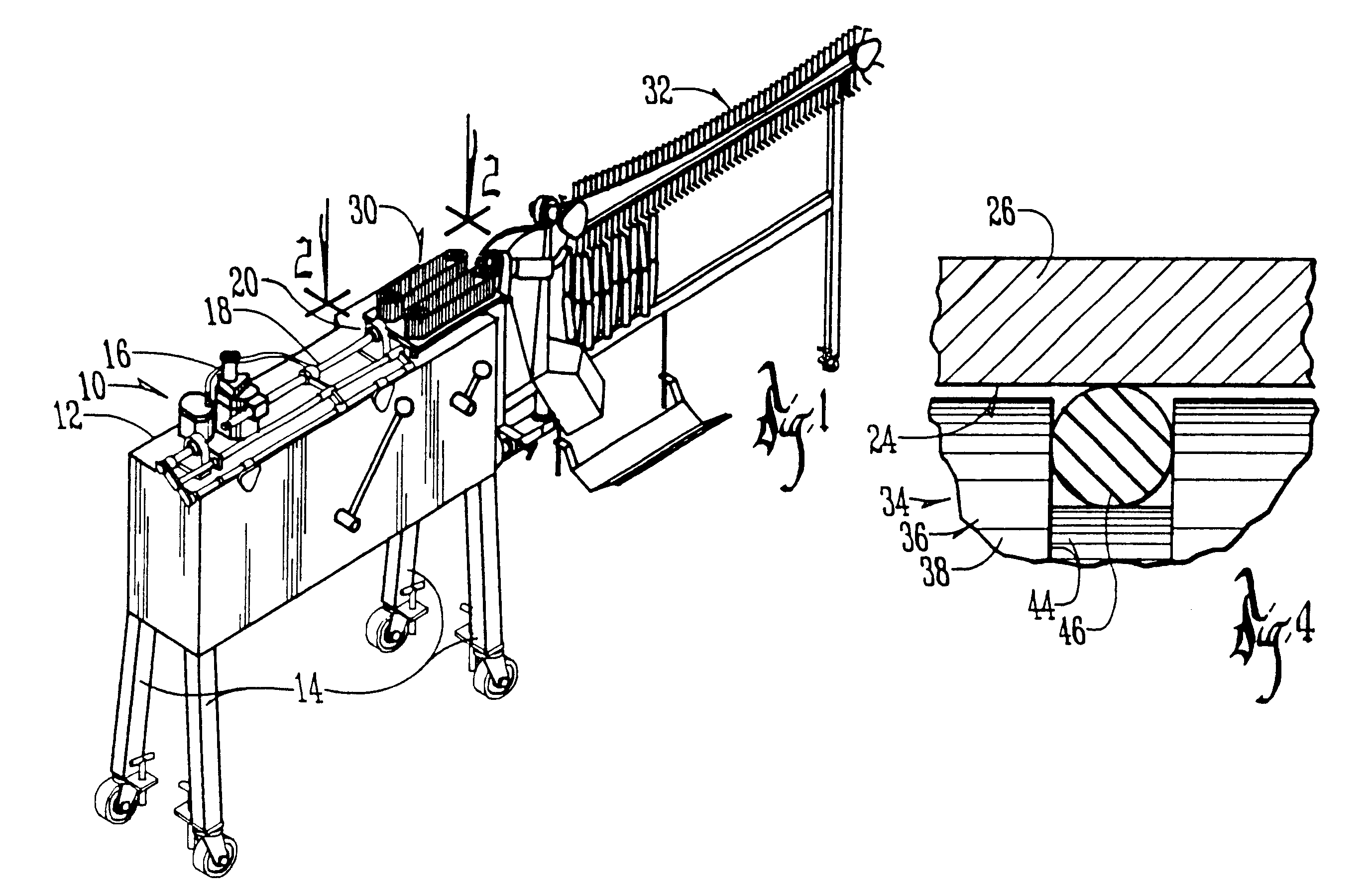
The conventional machine 10 in FIG. 1 has a frame 12 and supporting legs 14. A meat emulsion pump 16 is mounted on the top of frame 12 and is connected to a conventional elongated stuffing horn 18.

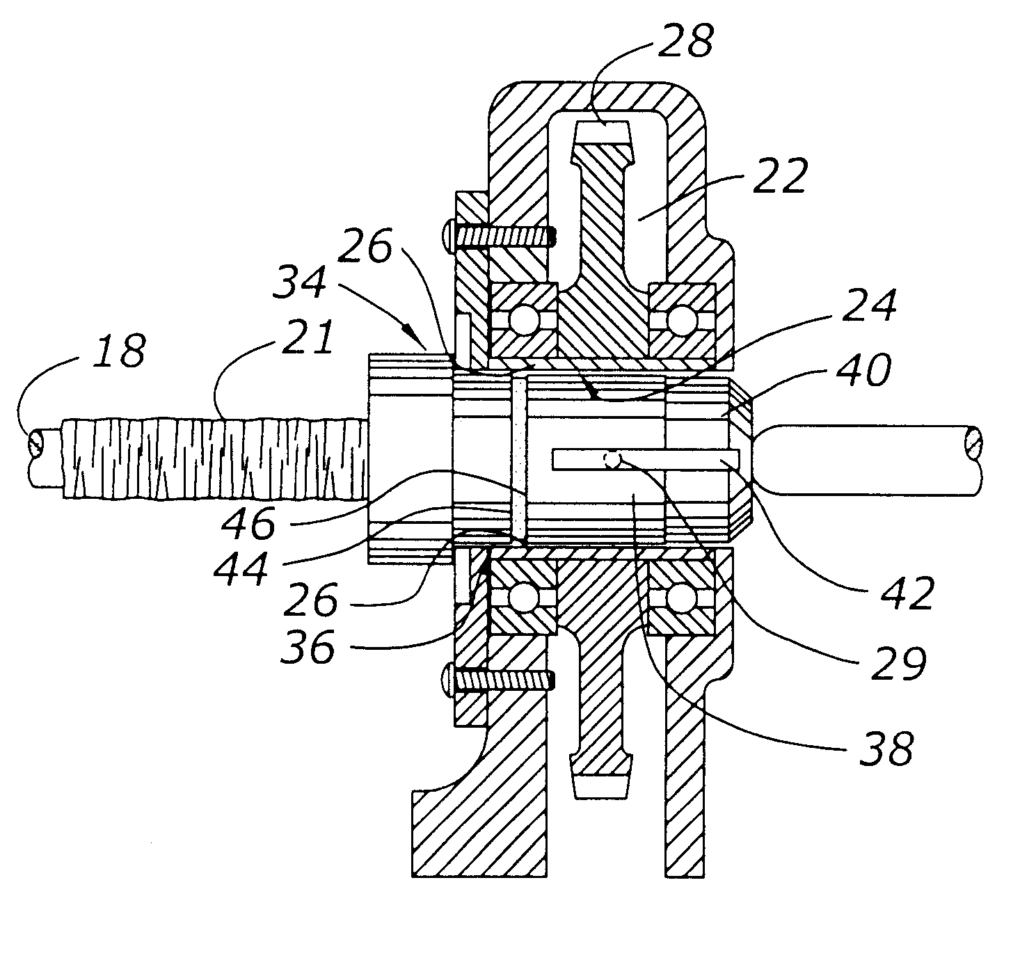
A drive housing 20 is mounted on the top of frame 12 and receives the discharge end of stuffing horn 18. A conventional shirred (telescopically compressed) casing 21 is mounted on stuffing horn 18.

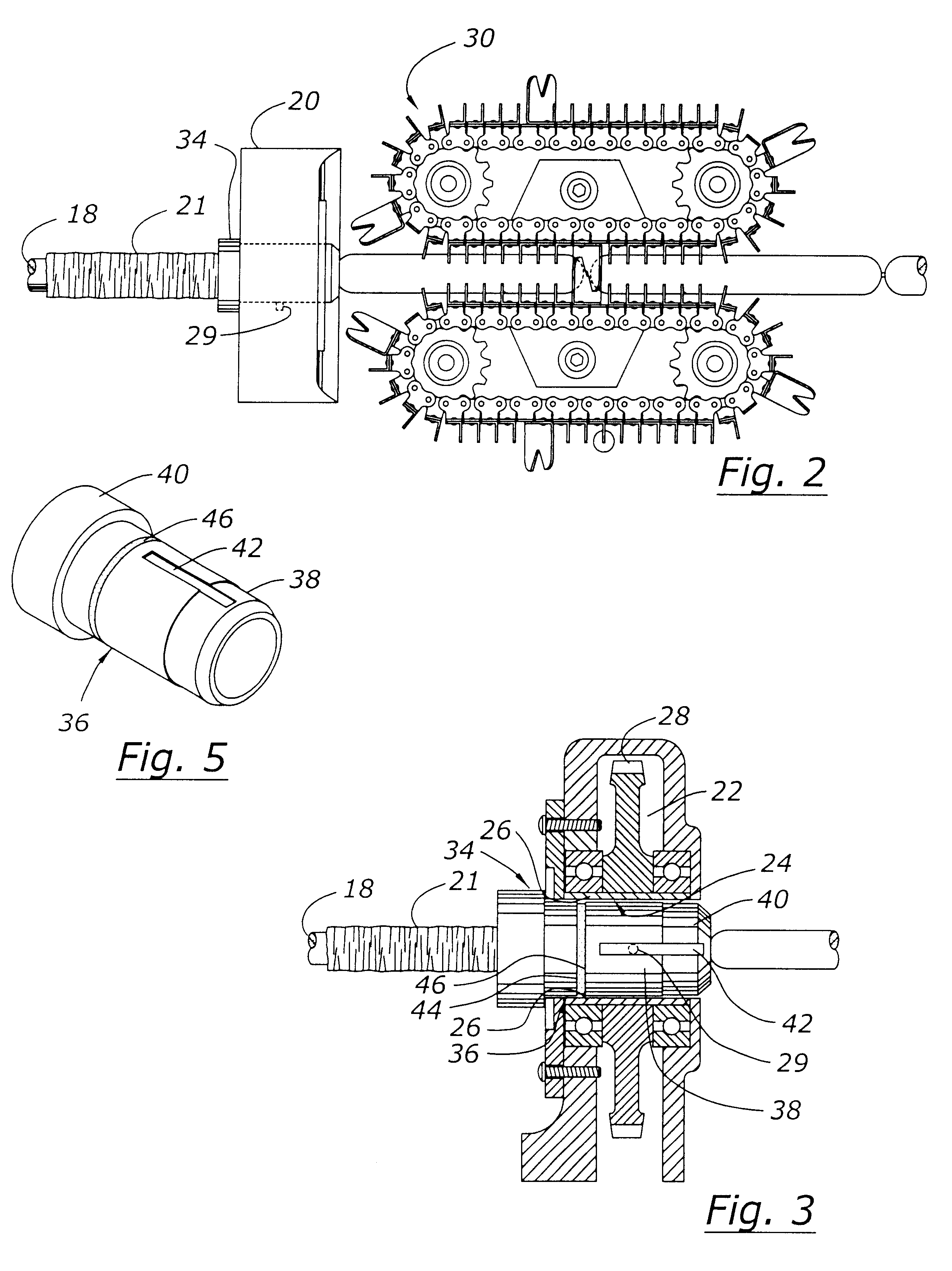
Drive housing 20 has a hollow interior compartment 22 and a hollow bore 24 extending therethrough. A bearing sleeve or socket 26 is mounted within housing 20 and is adapted to be rotatably driven by drive gear 28 which is connected to a source of rotational power (not shown). A drive pin 29 shown in dotted lines in FIGS. 2 and 3 extends inwardly from bearing sleeve 26 to engage and drive the chuck of this invention as will be described hereafter.

A conventional linking mechanism 30 is mounted on the top of frame 12 downstream from the discharge end of stuffing horn 18. Similarly, a conventional co...


PUM


Abstract

A chuck for a meat encasing machine has an elongated body having an inlet end and a discharge end. The body has an elongated hollow bore extending therethrough and an exterior cylindrical surface. A plurality of radially extending flutes are in the bore of the body for purposes of grasping and imparting rotational motion to a filled meat casing. An annular groove extends around the exterior cylindrical surface of the body member. A resilient O-ring is mounted in the groove and slightly projects outwardly from the groove to frictionally engage a socket into which the chuck is inserted.

Description

BACKGROUND OF THE INVENTIONMeat encasing machines for manufacturing sausages, wieners and the like have long existed in the prior art. Such a machine is shown in U.S. Pat. No. 3,115,688. These machines typically have an elongated stuffing horn upon which is mounted a shirred flexible casing. A hollow cylindrical chuck is mounted on the machine and receives the discharge end of the stuffing horn through which meat emulsion is extruded. The end of the stuffing horn and the shirred casing thereon are inserted into the casing which is rotated by a suitable drive mechanism. A chuck twists the casing as meat emulsion is extruded therein. A linking mechanism downstream from the discharge end of the stuffing horn serves to grasp the filled casing to hold it against rotation. Thus, the opposing forces exerted on the casing by the chuck and the linking mechanism cause the casing to twist at longitudinal increments defined by the distance between the discharge end of the chuck and the point wh...

Claims


Application Information

Patent Timeline
Patent Type & Authority Patents(United States)
IPC IPC(8): A22C11/02A22C11/00
CPCA22C11/02A22C11/0209
Inventor TOWNSEND, RAY T.
Owner STORK TOWNSEND BV
Why Eureka
Try Eureka