Miniature flashlight

a handheld flashlight and flashlight technology, applied in the field of flashlights, can solve the problems of inconvenient rotating head assembly switch, one hand can be spared for operating the flashlight, and the switch can be a bit cumbersome to operate the flashligh

Inactive Publication Date: 2003-03-04
MAG INSTR INC
View PDF33 Cites 37 Cited by
  • Summary
  • Abstract
  • Description
  • Claims
  • Application Information

AI Technical Summary

Benefits of technology

Another feature of the present invention is a means of protecting the raised positive terminals of dry cell batteries in flashlights by means of orienting the positive terminals away from the flashlight's head assembly and by providing a recess in the contact housing having a depth slightly less than the height of the battery's positive terminal and a width slightly greater than the width of the battery's positive terminal so the positive terminal is retained in the recess and is thereby protected from damage by said housing.

Problems solved by technology

In these situations, however, it is often the case that only one hand can be spared for operating the flashlight.
Unfortunately, it is somewhat cumbersome to actuate the flashlight by rotating the head assembly with one hand.
Furthermore, when the flashlight needs to be used as a flashing signal light, the rotating head assembly switch is inconvenient, even when two hands are used to operate the switch.
Unfortunately, it is in precisely these circumstances that the flashlight is most likely to be dropped and damaged.
If the flashlight is dropped, the disproportionately large percentage of the flashlight's mass located in the head assembly will give the flashlight a tendency to strike the ground head assembly first.
This type of a fall will cause the flashlight's batteries to be driven against the forward wall of the battery retainer, thereby causing a disproportionately large percentage of the impact to be borne by the raised nipple of the positive terminal of the battery which rests against the front wall of the retainer.
As a result of this impact force, the nipple may be crushed or dented; thereby, in view of the very small contact area of these miniature batteries, potentially interrupting the flashlight's electrical circuit.

Method used


Image

  • Miniature flashlight
  • Miniature flashlight
  • Miniature flashlight

Examples


Embodiment Construction

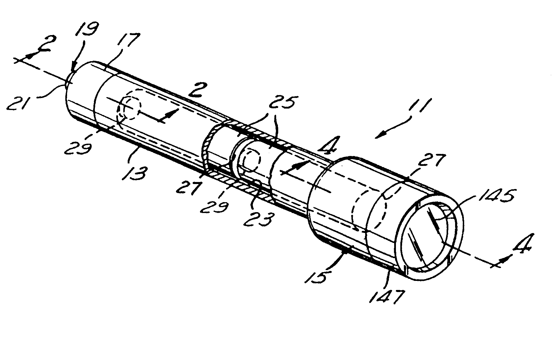
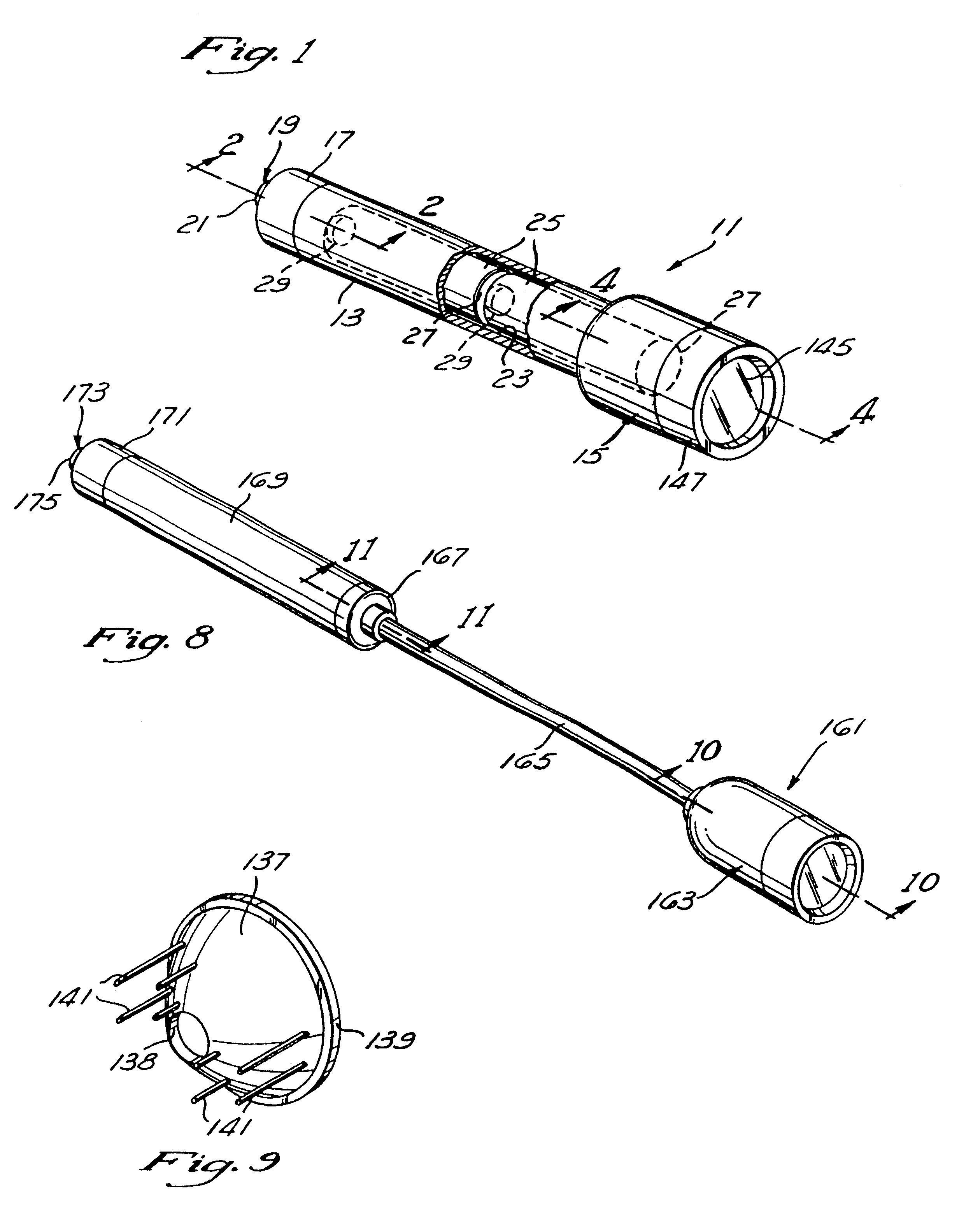
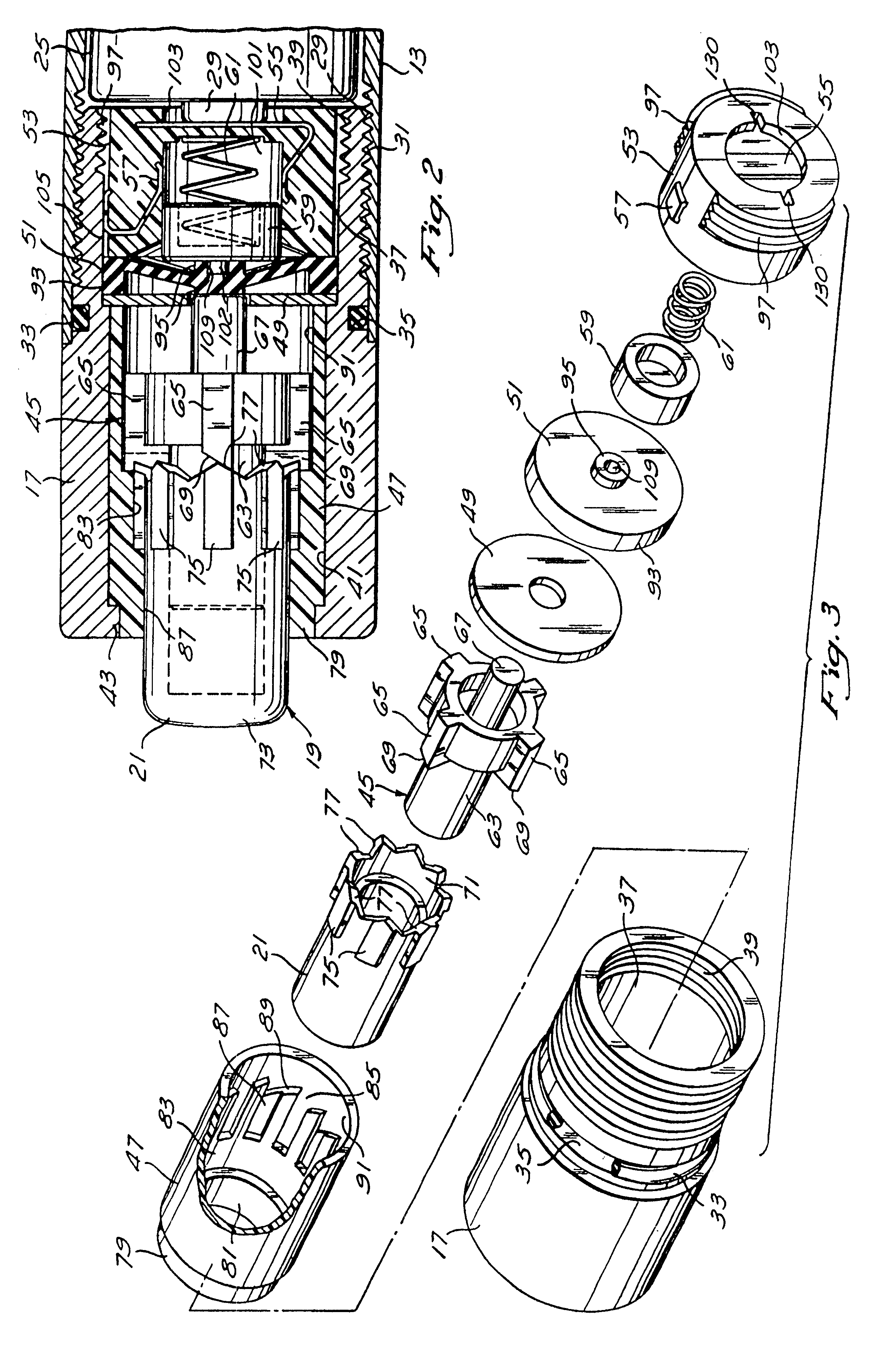
Referring to FIG. 1, there is shown a miniature flashlight 11 having a generally cylindrical, elongate battery retainer 13, a larger diameter, generally cylindrical head assembly 15 secured to one end of the retainer 13, and a generally cylindrical end cap 17 having a diameter essentially equivalent to that of the retainer 13, secured to the opposite end of the retainer. As better shown in FIG. 2, the flashlight's electrical circuit is opened and closed by means of a switch mechanism 19 located in the end cap 17 which is operated by depressing a cup-shaped button 21.

In its preferred embodiment, the battery retainer 13 is fabricated from anodized, heat treated aluminum and the retainer defines a hollow, generally cylindrical chamber 23 for holding two AA dry-cell batteries in series.

As shown in phantom in FIG. 1, a pair of dry cell batteries 25 are oriented so that their negative terminals 27 face the head assembly 15 and their positive terminals 29 face the end cap 17. This arrangem...


PUM


Abstract

A waterproof flashlight wherein the flashlight is activated by means of a switch located in the flashlight's end cap. Another aspect of the invention being the orientation of the positive terminals of the flashlight's batteries away from the head assembly.

Description

BACKGROUND OF THE INVENTIONThe present invention relates primarily to flashlights, and in particular, to miniature hand-held flashlights.Although miniature flashlights have long been known in the art, it is only been recently, with the development of miniature flashlight lamp bulbs having superior light-emitting characteristics and with improvements in the reflective quality of in flashlight reflectors, that there has developed a genus of high quality miniature flashlights.U.S. Pat. No. 4,577,263 issued to Maglica discloses one member of this genus. Maglica discloses a high quality, hermetically-sealed miniature flashlight having a rotating head assembly which is used to vary the relative positions of the bulb and the reflector in order to adjust the flashlight beam from broad and diffuse to narrow and concentrated. By continuing to rotate the head assembly so that it is translated towards the tail cap of the flashlight, the circuit between the bulb and the batteries is opened and t...

Claims


Application Information

Patent Timeline
Patent Type & Authority Patents(United States)
IPC IPC(8): F21L4/00F21L4/06F21V23/04
CPCF21L2/00F21V23/0414F21V23/0421
Inventor BIEBERSTEIN, LEE K.
Owner MAG INSTR INC
Why Eureka
Try Eureka