
Bicycle wheel travel path for selectively applying chainstay lengthening effect and apparatus for providing same

a technology of chainstay lengthening effect and travel path, which is applied in the field of rear suspension system, can solve the problems of not being completely satisfactory in practice and needlessly wasteing rider's energy

Inactive Publication Date: 2006-07-11
SANTA CRUZ BICYCLES
View PDF13 Cites 55 Cited by
  • Summary
  • Abstract
  • Description
  • Claims
  • Application Information

AI Technical Summary

Benefits of technology

[0006]The present invention has solved the problems cited above. Broadly, this is a bicycle comprising: a chain drive in which the distance from the axis of a drive sprocket to the axis of a rear wheel hub is represented by a variable value CSL; and a compressible rear suspension having a linkage for moving the hub along a controlled wheel travel path as the suspension is compressed, the controlled wheel travel path having an arc radius which is greater towards a lower end of the path and smaller towards an upper end of the path.

Problems solved by technology

In general, however, these have not proven entirely satisfactory in practice.
In this respect, the spring / damper assembly of the rear suspension is affected by the pedal force and some of the rider's energy is needlessly wasted.

Method used


Image

  • Bicycle wheel travel path for selectively applying chainstay lengthening effect and apparatus for providing same
  • Bicycle wheel travel path for selectively applying chainstay lengthening effect and apparatus for providing same
  • Bicycle wheel travel path for selectively applying chainstay lengthening effect and apparatus for providing same

Examples


Embodiment Construction

a. Overview

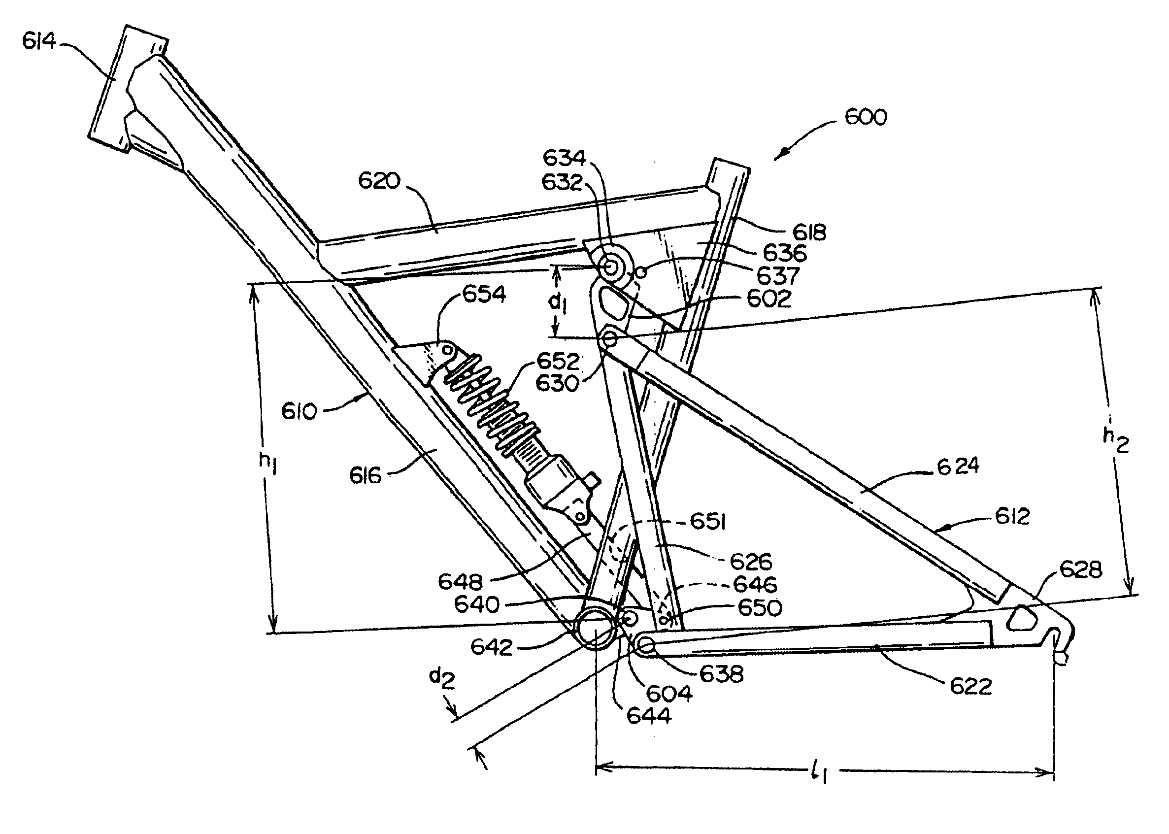
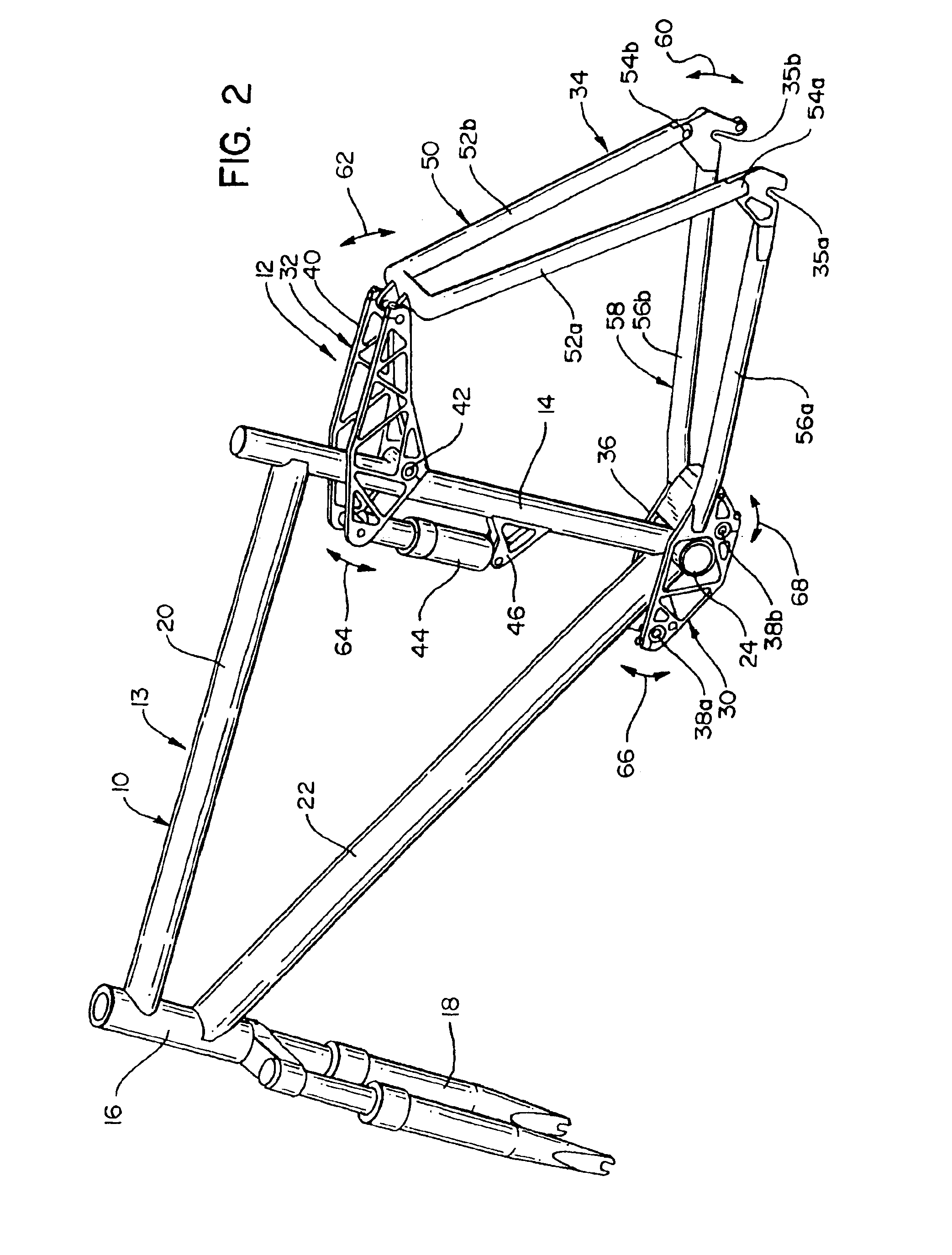
[0048]The present invention provides a rear suspension system which effectively absorbs forces which are received due to irregular terrain, but which minimizes the compression / extension of the suspension by forces which are applied by the rider during vigorous and / or uneven pedaling. This is accomplished by means of a dual eccentric crank mechanism which moves the rear wheel along a predetermined path as the suspension is compressed, so that the chain tension works to counteract the downward forces on the frame during selected phases of the compression cycle.

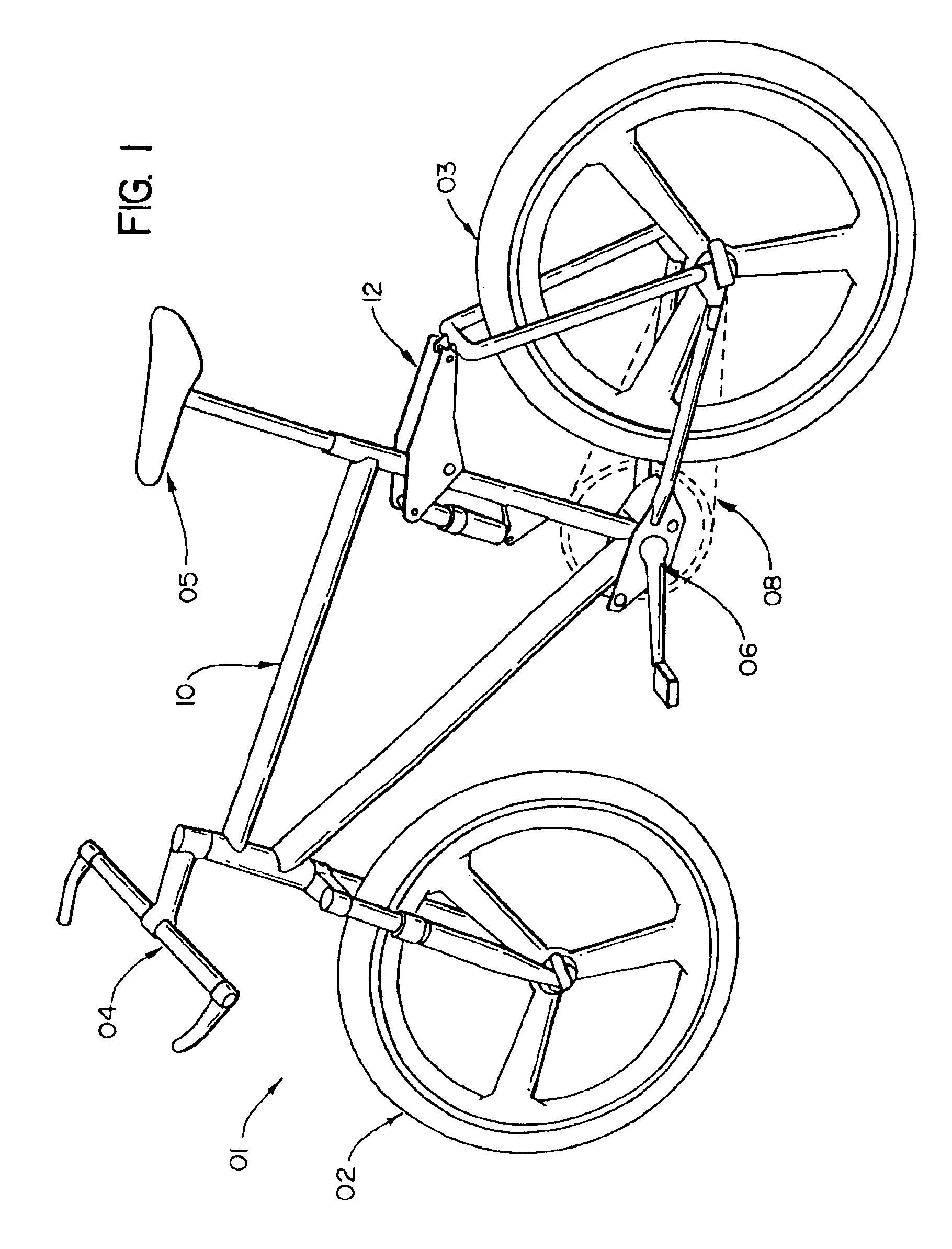
[0049]FIG. 1 is a perspective view of a bicycle 01 having a frame 10 which incorporates a rear suspensions system 12 in accordance with the present invention. The frame and suspension system have attachment fittings for the following components, which are of generally conventional configuration and therefore do not themselves form a part of the present invention: Front and rear wheels 02, 03, handle bar assembly 04, s...


PUM


Abstract

A rear suspension system for a bicycle. The system directs the rear wheel along a predetermined, S-shaped path as the suspension is compressed. The path is configured to provide a chainstay lengthening effect only at those points where this is needed to counterbalance the pedal inputs of the rider; at those points on the wheel travel path where there is a chainstay lengthening effect, the chain tension which results from the pedal inputs exerts a downward force on the rear wheel, preventing unwanted compression of the suspension. The system employs a dual eccentric crank mechanism mounted adjacent the bottom bracket shell to provide the desired control characteristics.

Description

[0001]This application is a continuation-in-part of U.S. Ser. No. 08 / 724,303, filed Sep. 19, 1996, abandoned Apr. 22, 1999; which is a continuation-in-part of U.S. Ser. No. 08 / 558,162, filed Nov. 15, 1995 (U.S. Pat. No. 5,628,524, issued May 13, 1997); which is a continuation-in-part of U.S. Ser. No. 08 / 377,931, filed Jan. 25, 1995 (U.S. Pat. No. 5,553,881, issued Sep. 10, 1996). This application claims benefit of provisional application Ser. No. 60 / 040,702 filed Mar. 13, 1997.FIELD OF THE INVENTION[0002]The present invention relates generally to bicycles, and more particularly to a rear suspension system which provides efficient energy transmission but still provides compliant suspension action when the bicycle is ridden over rough terrain.BACKGROUND OF THE INVENTION[0003]Shock absorbing rear suspensions for bicycles are known. In general, however, these have not proven entirely satisfactory in practice.[0004]In most rear suspension assemblies, the rear axle pivots about a single p...

Claims


Application Information

Patent Timeline
Patent Type & Authority Patents(United States)
IPC IPC(8): B62K25/28
CPCB62K25/286
Inventor KLASSEN, JAMES B.CALON, JAMIE W.
Owner SANTA CRUZ BICYCLES
Features
  • Generate Ideas
  • Intellectual Property
  • Life Sciences
  • Materials
  • Tech Scout
  • Unparalleled Data Quality
  • Higher Quality Content
  • 60% Fewer Hallucinations
Learn More