Fuel pipeline structure of vehicle

A technology for fuel pipelines and vehicles, which is applied to liquid fuel feeders, charging systems, combustion engines, etc. It can solve the problems of large size, increased weight, difficulty in ensuring space, and increased weight, etc., to achieve lightweight , shorten the wheel space, reduce the effect of vibration space

Active Publication Date: 2007-10-24
HONDA MOTOR CO LTD
View PDF5 Cites 0 Cited by
  • Summary
  • Abstract
  • Description
  • Claims
  • Application Information

AI Technical Summary

Problems solved by technology

In addition, around the fuel pipe 212, especially in the vertical direction, it is necessary to provide a space for the fuel pipe 212 to vibrate. Such a space makes the vehicle larger.
Especially in small vehicles, it is difficult to guarantee this kind of space
[0007] In addition, if the fuel pipe 212 is too long, its weight will increase, and when the fuel pipe 212 vibrates, a large force will act on the mounting part of the fuel pipe 212. In order to support this force, the rigidity of the above-mentioned mounting part must be increased. , resulting in an increase in size and weight

Method used


Image

  • Fuel pipeline structure of vehicle
  • Fuel pipeline structure of vehicle
  • Fuel pipeline structure of vehicle

Examples


Embodiment Construction

[0036] Specific embodiments of the present invention will be described below with reference to the accompanying drawings. In addition, the drawings are viewed towards the symbol.

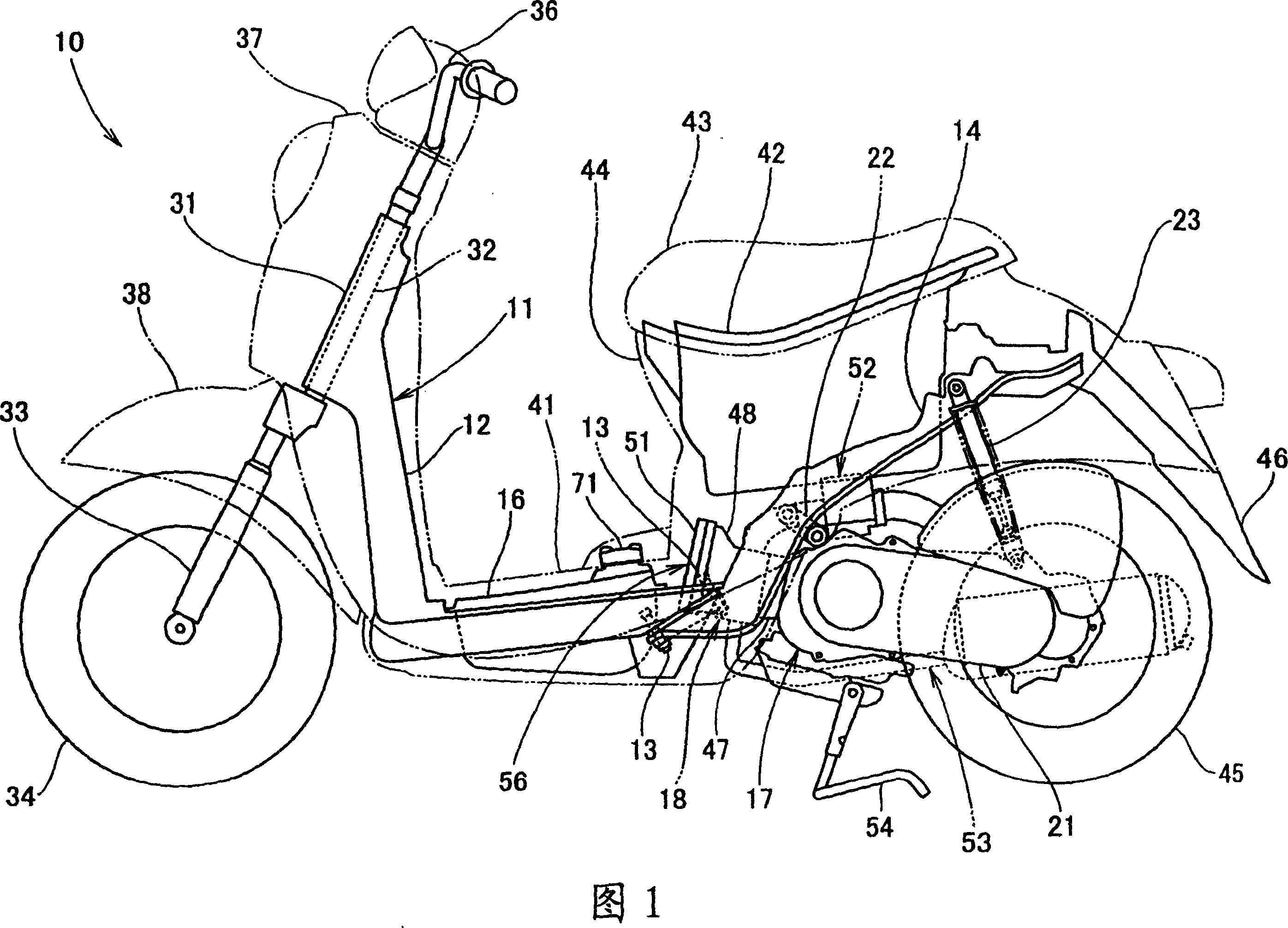
[0037] Fig. 1 is the side view of vehicle of the present invention, and the vehicle frame 11 of vehicle 10 is installed on the rear frame of the rear portion of this front frame 12 by front frame 12 and with bolt 13... (... represents a plurality of, hereinafter the same) 14, a fuel tank 16 is mounted on the lower part of the front frame 12, and a power assembly 17 that is substantially horizontal in the front and rear direction of the vehicle (by the engine 18 and connected to the rear frame 14) The power transmission mechanism 21 on the engine 18 constitutes), the rear portion of the power assembly 17 is installed on the rear portion of the rear frame 14 by the rear shock absorber assembly 23, is such a two-wheeled motorcycle.

[0038] Here, 31 is a head pipe mounted on the front frame 12, 32 is ...


PUM


Abstract

The purpose of the invention is to compact a vehicle by reducing vibration amount of a fuel pipe, to reduce the rigidity of a pipe mounting part by reducing an operation force to the fuel pipe mounting part, and to miniaturize and lighten the vehicle. In the vehicle, a power unit having an internal combustion engine body is swing-ably mounted on a vehicle body frame with a cylinder head directed to the front side of the vehicle body, a fuel pump is connected to a fuel tank mounted on the vehicle body frame, a fuel injection valve is disposed in an air intake passage of the internal combustion engine body, and the fuel pump is connected to the fuel injection valve through the fuel pipe. A second hose 84 of the fuel pipe is provided with at least a head cover side extension section 125 extended in the swing direction around the internal combustion engine body including a head cover 51. Part of the head cover side extension section 125 is supported by a first supporting member 97 and a second supporting member 98 which are disposed in the internal combustion engine body 56.

Description

technical field [0001] The invention relates to a vehicle fuel pipeline structure. Background technique [0002] As a conventional fuel line structure for a vehicle, a fuel line extending from a fuel tank provided under a running board to an engine disposed behind the fuel tank is known (for example, refer to Patent Document 1). [0003] Patent Document 1: Japanese Patent Application Laid-Open No. 2003-120450. [0004] FIG. 2 of Patent Document 1 will now be explained with reference to FIG. 9 below. Also, the symbols are relabeled. [0005] 9 is a plan view showing a conventional vehicle fuel pipeline structure. An engine 202 and a fuel tank 203 arranged in front of the engine 202 are installed on a body frame 201. A fuel supply assembly 204 is integrally installed on the fuel tank 203. The engine 202 A fuel injection valve (not shown) is installed on the cylinder part 206 of the fuel supply assembly 204 through a fuel connector 207, and the fuel output pipe 208 provided ...

Claims


Application Information

Patent Timeline
Patent Type & Authority Patents(China)
IPC IPC(8): F02M37/00B62J37/00B62J25/00B62J35/00F02F1/24F02M37/10
CPCY02T10/123Y02T10/12B62J37/00
Inventor 大城健史池田健一郎八木泽胜一
Owner HONDA MOTOR CO LTD
Why Eureka
Try Eureka