
speaker module

A loudspeaker module and loudspeaker technology, applied in the direction of frequency/directional characteristic device, etc., can solve the problems such as the inability to meet the development direction of the miniaturization of the loudspeaker module, the noise of the loudspeaker module, the waste of vibration space, etc., to meet the requirements of the miniaturization development, vibration The effect of displacement equalization and high acoustic performance

Active Publication Date: 2017-01-11
GOERTEK INC
View PDF6 Cites 0 Cited by
  • Summary
  • Abstract
  • Description
  • Claims
  • Application Information

AI Technical Summary

Problems solved by technology

On the side where the vibration displacement of the diaphragm is large, the diaphragm will collide with other components, causing noise in the speaker module. In order to avoid the collision between the diaphragm and other components, it is necessary to increase the vibration space, which cannot meet the miniaturization of the speaker module. Development direction; on the side where the vibration displacement of the diaphragm is small, it will cause a waste of vibration space

Method used


Image

  • speaker module
  • speaker module
  • speaker module

Examples


Embodiment 1

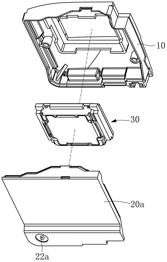
[0023] Such as figure 1 As shown, a loudspeaker module includes a combined module upper case 10 and a module lower case 20a, the space enclosed by the module upper case 10 and the module lower case 20a accommodates a speaker unit 30, and the speaker A rear acoustic cavity is formed between the unit 30 and the module lower shell 20a. A sound leakage hole 22a for adjusting the air pressure in the inner cavity of the module is provided at the position corresponding to the rear acoustic cavity on the lower module shell 20a.

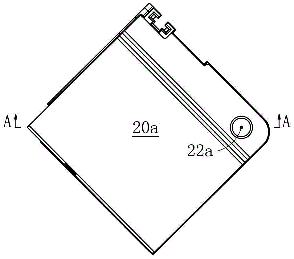
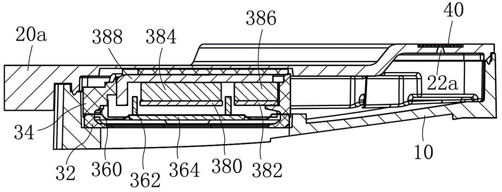
[0024] Such as figure 2 with image 3 Commonly shown, the side of the module lower case 20a close to the speaker unit 30 is defined as the inner side, the other side is the outer side, the sound leakage hole 22a is a conical structure, and the sound leakage hole 22a is located at one end of the outer side of the module lower case 20a The caliber is smaller, and one port located on the inner side of the module lower case 20a has a larger caliber. A dampin...

Embodiment 2

[0031] Such as Figure 5 As shown, the present embodiment is basically the same as Embodiment 1, the difference is:

[0032] The diameter of the sound leakage hole 22b located on the inner side of the module lower case 20b is smaller, and the diameter of the sound leakage hole 22b located on the outer side of the module lower case 20b is larger.

[0033] In this embodiment, the resistance of the air flow from the inner cavity of the module to the outside is large, and the resistance of the air flow from the outside to the inner cavity of the module is small, so that the air pressure inside the module is greater than the outside air pressure, and the downward vibration displacement of the diaphragm can be reduced , suitable for loudspeaker modules with large downward vibration displacement of the diaphragm.

[0034] The definition of the module upper shell and the module lower shell in the present invention is a common term in the field, and the side where the sound of the spe...


PUM


Abstract

The invention discloses a loudspeaker module and relates to the technical field of electroacoustic products. The loudspeaker module comprises a module shell, wherein a loudspeaker single body is placed in the module shell, a sound releasing hole used for adjusting air pressure in the module is formed in the module shell, a rear sound cavity is formed between the loudspeaker single body and the module shell, the sound releasing hole is formed in the position, corresponding to the rear sound cavity, of the module shell, the sound releasing hole is of a conic structure, and the diameters of the portions, located on the two sides of the module shell, of the sound releasing hole are different. The loudspeaker module has the advantages that the vibration space of a single side can be saved under the condition that space is limited, and requirements for miniaturization development of loudspeaker modules are met; noise can not be generated, and acoustic performance is high; radiating performance is good, and the service life is long.

Description

technical field [0001] The invention relates to the technical field of electroacoustic products, in particular to a loudspeaker module. Background technique [0002] The loudspeaker module is an important acoustic component of portable electronic equipment. It includes a housing, in which a speaker unit is accommodated, and a rear acoustic cavity is formed between the speaker unit and the housing. The rear acoustic cavity is the space behind the diaphragm of the speaker unit. In order to prolong the service life of the speaker module and improve the acoustic performance of the speaker module, technicians usually set a sound leak hole on the module shell, which can maintain the exchange of airflow inside and outside the module and balance the inner cavity of the module. Air pressure, but also play the role of heat dissipation. [0003] The sound leakage hole structure in the prior art is a cylindrical structure. With the continuous miniaturization of the speaker module, the ...

Claims


Application Information

Patent Timeline
Patent Type & Authority Patents(China)
IPC IPC(8): H04R1/20
Inventor 朱婷刘光磊许超
Owner GOERTEK INC
Learn More