
Multi-chip semiconductor packaging structure and manufacturing method

A packaging structure and semiconductor technology, applied in semiconductor/solid-state device manufacturing, semiconductor devices, semiconductor/solid-state device components, etc., to meet the needs of miniaturization development, realize system packaging, and reduce packaging volume

Active Publication Date: 2017-02-22
HUATIAN TECH KUNSHAN ELECTRONICS
View PDF8 Cites 0 Cited by
  • Summary
  • Abstract
  • Description
  • Claims
  • Application Information

AI Technical Summary

Problems solved by technology

[0003] However, to integrate multiple chips in a limited chip area, the packaging thickness, reliability and cost of materials need to be solved

Method used


Image

  • Multi-chip semiconductor packaging structure and manufacturing method
  • Multi-chip semiconductor packaging structure and manufacturing method
  • Multi-chip semiconductor packaging structure and manufacturing method

Examples


Embodiment 1

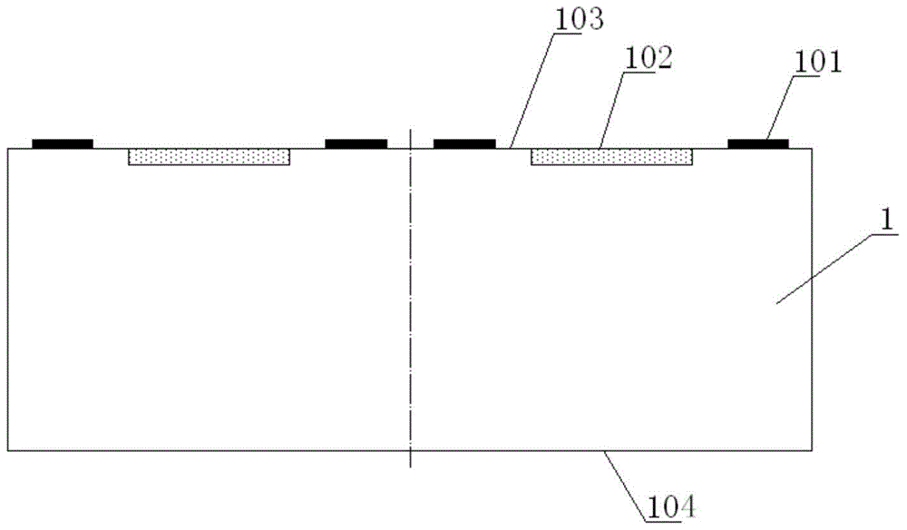
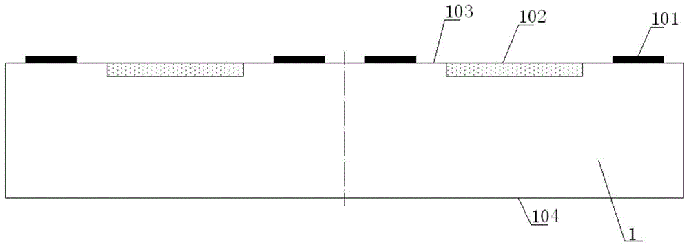
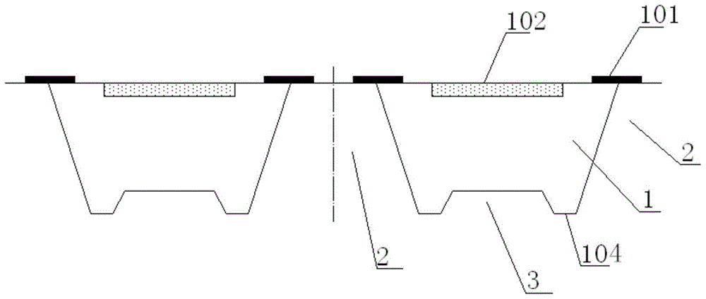
[0051] Such as Figure 12 As shown, a multi-chip semiconductor packaging structure includes a semiconductor bare chip 1, the semiconductor bare chip has a first surface 103 and a second surface 104 opposite to it; the first surface has an element region 102 and is located on the Several first pads 101 around the component area, the component area is used to receive the light source or user fingerprint information, the first pads are electrically connected to the component area; the second surface is formed with a The opening 2 and the groove 3, and the groove is opposite to the element area, the opening is opposite to the first pad and exposes the first pad; the second surface, the groove A first insulating layer 4, a metal wiring layer 5 and a second insulating layer 6 are sequentially formed on the inner wall and the inner wall of the opening, and the second insulating layer covers the metal wiring layer for protecting the metal wiring layer from being oxidized Corrosion, a...

Embodiment 2

[0072] This embodiment 2 includes all the technical features in the embodiment, such as Figure 13 As shown, the difference is that a protective layer 11 is provided on the element region. The protective layer is used to protect the sensing area of ​​the sensor chip from damage. Optionally, the material of the protective layer is protective materials such as glass or film and glass ceramics. Preferably, the thickness of the protective layer is between 1-400 between microns.

[0073] To sum up, the present invention proposes a multi-chip semiconductor packaging structure and manufacturing method, and the grooves in the packaging structure provide favorable conditions for reducing the thickness of the packaging. Using the groove structure, other functional chips are placed in it, through The redistribution process interconnects the lines and realizes system packaging. Therefore, the packaging structure can reduce the packaging thickness and meet the requirements for the miniat...


PUM


Abstract

The invention discloses a multi-chip semiconductor packaging structure and a manufacturing method. The packaging structure includes a semiconductor chip. The second surface of the semiconductor chip is formed with an opening and a groove extending toward the first surface, and the groove is connected to the components of the semiconductor chip. The region faces away, the opening faces away from the first pad of the semiconductor chip and exposes the first pad; the second surface, the inner wall of the groove and the inner wall of the opening are sequentially formed with a first insulating layer, a metal wiring layer and a second insulating layer , at least one functional chip is placed in the groove, and other vacant spaces in the groove are filled with insulating materials, and the metal wiring layer is electrically connected to the first pad and the pad of the functional chip. This packaging structure can be used without increasing the thickness of the package Based on the system packaging, the manufacturing method of the packaging structure utilizes the wafer-level chip size packaging technology, and the overall packaging is performed first, and then the wafer is cut into individual chips, which reduces the production cost.

Description

technical field [0001] The invention relates to a semiconductor packaging structure and technology, in particular to a multi-chip semiconductor packaging structure and a manufacturing method. Background technique [0002] With the increasing diversification of requirements for memory characteristics of various portable information devices and the development trend of short, small, light and thin electronic products, the current development direction of semiconductor bare chip packaging structure is to package several chips in one system. Multi-chip (Multi-Chip Package, MCP) packaging structure. It is used to achieve the requirements of multiple functions or multiple performances on one package. The multi-chip packaging structure is to integrate different types of chips, such as memory chips, memory chips, flash chips, etc., into one package. [0003] However, to integrate multiple chips in a limited chip area, the packaging thickness, reliability and cost of materials need...

Claims


Application Information

Patent Timeline
Patent Type & Authority Patents(China)
IPC IPC(8): H01L23/498H01L21/48H01L25/04
CPCH01L2224/73267H01L2224/82H01L2224/92244H01L2924/15153H01L2224/04105H01L2224/11H01L2224/12105H01L2224/19H01L2224/24137H01L2224/24145H01L2224/32145
Inventor 王晔晔万里兮黄小花沈建树钱静娴翟玲玲廖建亚金凯邹益朝王珍
Owner HUATIAN TECH KUNSHAN ELECTRONICS
Learn More