
Linear Vibration Motor

A linear vibration and motor technology, applied in electromechanical devices, electrical components, etc., can solve the problems of poor vibration stability, poor rigidity of shrapnel, and unreasonable elastic support structure.

Active Publication Date: 2018-03-06
GOERTEK INC
View PDF5 Cites 0 Cited by
  • Summary
  • Abstract
  • Description
  • Claims
  • Application Information

AI Technical Summary

Problems solved by technology

In the prior art, square or rectangular motors usually vibrate on the largest surface, and the distance between the fulcrums of the vibrator is large. The design of the shrapnel is particularly important. With a single or double shrapnel structure, the rigidity of the shrapnel in dimensions other than the vibration direction is poor, and single fulcrums are prone to three. Dimensional deflection, double fulcrums are prone to two-dimensional rotation around the axis
[0005] It can be seen that the current square or rectangular Z / Y linear motor has a serious first-order natural frequency polarization problem due to the unreasonable structure of the elastic support, poor vibration stability, and prone to vibration deflection, resulting in collision noise

Method used


Image

  • Linear Vibration Motor
  • Linear Vibration Motor
  • Linear Vibration Motor

Examples


Embodiment Construction

[0030] In the following description, for purposes of explanation, numerous specific details are set forth in order to provide a thorough understanding of one or more embodiments. It may be evident, however, that these embodiments may be practiced without these specific details. In other instances, well-known structures and devices are shown in block diagram form in order to facilitate describing one or more embodiments.

[0031] The "mass block" used in the description of the following specific embodiments may also be referred to as a "counterweight block", which refers to a high-quality, high-density metal block that is fixed to the vibrating block that generates vibration to enhance vibration balance. In addition, the invention is mainly used for the improvement of miniature vibration motors, but it does not exclude the application of the technology in the invention to large vibration motors. However, for the convenience of expression, in the description of the following em...


PUM


Abstract

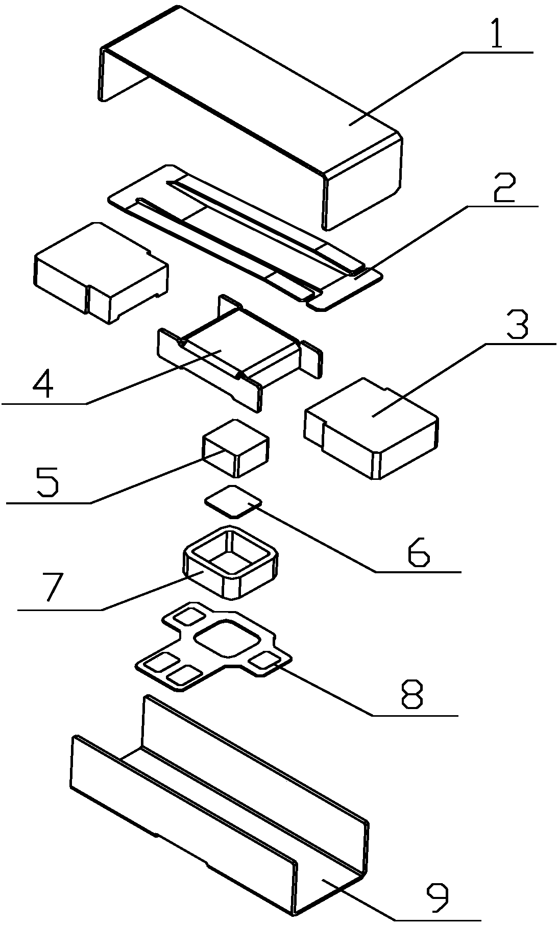
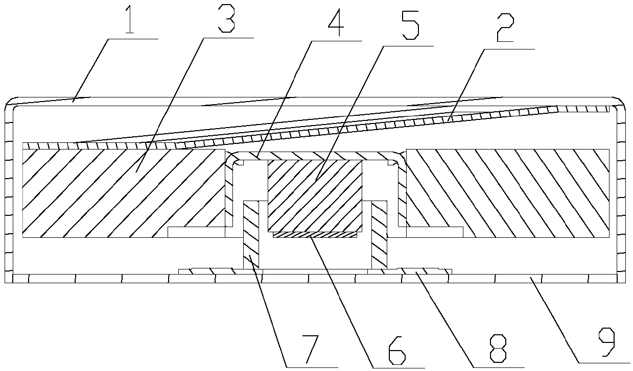
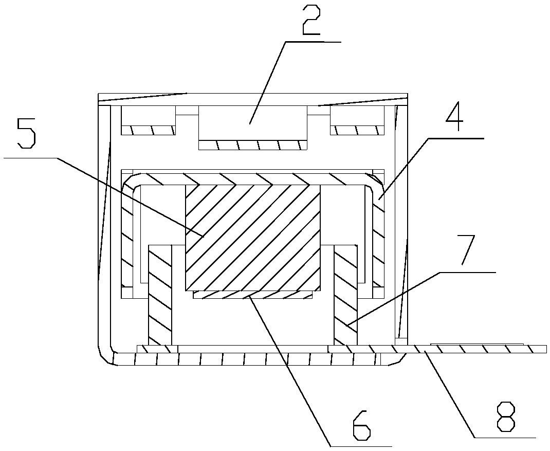
A linear vibration motor, comprising a housing and a vibration assembly accommodated in the housing. The vibration assembly comprises a mass (3) and an elastic support member (2); the elastic support member (2) is disposed between the upper end surface of the mass (3) and the inner surface of the top of the housing, to suspend the mass (3) in the housing by means of the elastic support member (2); the elastic support member (2) is of a sheet structure, and comprises a first fixed end (21), a second fixed end (22), and a connecting arm (23) disposed between the first fixed end (21) and the second fixed end (22), and symmetrically distributed cantilevers (24) are provided at both sides of the connecting arm (23); one of the first fixed end (21) and the second fixed end (22) is fixed on the mass (3), and the other of the first fixed end (21) and the second fixed end (22) is fixed on the housing. The solution can simplify the structure of the elastic support member, and achieve stable vibration of the vibration assembly.

Description

technical field [0001] The present invention relates to the technical field of consumer electronic products, and more specifically, relates to a linear vibration motor. Background technique [0002] With the development of communication technology, portable electronic products, such as mobile phones, handheld game consoles or handheld multimedia entertainment devices, have entered people's lives. In these portable electronic products, micro-vibration motors are generally used for system feedback, such as mobile phone call notifications, game console vibration feedback, and so on. However, with the development trend of thinner and lighter electronic products, various internal components also need to adapt to this trend, and the micro vibration motor is no exception. [0003] Existing miniature vibrating motors generally include an upper cover, a lower cover forming a vibration space with the upper cover, a vibrator (including a mass and a permanent magnet) that vibrates line...

Claims


Application Information

Patent Timeline
Patent Type & Authority Patents(China)
IPC IPC(8): H02K33/02
CPCH02K33/02
Inventor 史德璋朱跃光
Owner GOERTEK INC
Learn More