Eureka AIR delivers breakthrough ideas for toughest innovation challenges, trusted by R&D personnel around the world.

Linear Vibration Motor

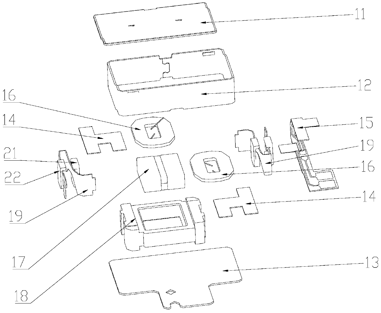
A linear vibration and motor technology, applied in the direction of electromechanical devices, electrical components, etc., can solve the problems of poor vibration experience of linear vibration motors and difficult to improve the acceleration value.

Active Publication Date: 2020-02-21
GOERTEK INC
View PDF4 Cites 0 Cited by
  • Summary
  • Abstract
  • Description
  • Claims
  • Application Information

AI Technical Summary

Problems solved by technology

Due to the constant stiffness, linear vibration motors are used in high-frequency applications (for example, frequencies greater than F 0 ) The acceleration value is difficult to increase, resulting in poor vibration experience of the linear vibration motor

Method used


Image

  • Linear Vibration Motor
  • Linear Vibration Motor
  • Linear Vibration Motor

Examples


Embodiment Construction

[0024] Various exemplary embodiments of the present invention will now be described in detail with reference to the accompanying drawings. It should be noted that the relative arrangements of components and steps, numerical expressions and numerical values ​​set forth in these embodiments do not limit the scope of the present invention unless specifically stated otherwise.

[0025] The following description of at least one exemplary embodiment is merely illustrative in nature and in no way taken as limiting the invention, its application or uses.

[0026] Techniques, methods and devices known to those of ordinary skill in the relevant art may not be discussed in detail, but where appropriate, such techniques, methods and devices should be considered part of the description.

[0027] In all examples shown and discussed herein, any specific values ​​should be construed as exemplary only, and not as limitations. Therefore, other instances of the exemplary embodiment may have dif...


PUM


Abstract

The invention discloses a linear vibration motor. The linear vibration motor comprises a vibrator assembly, a stator assembly and an elastic element. The vibrator assembly is connected to the stator assembly through the elastic element, the vibrator assembly is subjected to the action of electromagnetic force of the stator assembly and generates vibration, magnets are installed at the two ends ofthe vibration direction of the stator assembly, the magnets are adhesively connected to the stator assembly or connected to the stator assembly in a injection molding mode, the stator assembly is provided with magnetic elements, the magnetic elements corresponds to the magnets one by one, and repulsive force is formed between the magnetic elements and corresponding magnets. The rigidity of the linear vibration motor presents as a non-linear change, and therefore improves vibration sense experience.

Description

technical field [0001] The present invention relates to the technical field of vibration devices, and more particularly, to a linear vibration motor. Background technique [0002] Currently, a linear vibration motor includes a vibrator assembly, a stator assembly, and an elastic element. The stator assembly includes the shell, the coil, the FPCB, the limiting parts and so on. The coil and the FPCB are fixed on the bottom wall or the top wall of the housing. The vibrator assembly is suspended in the housing through the elastic element. The elastic element provides elastic recovery force, for example, the elastic element is a shrapnel. The limiting component is located on the side of the vibrator assembly to damp the vibrator assembly. The vibrator assembly includes a mass block, a magnet assembly, and the like. The magnetic assembly is acted upon by the electromagnetic force of the coil. The vibrator assembly vibrates under the action of the electromagnetic force. [0...

Claims


Application Information

Patent Timeline
Patent Type & Authority Patents(China)
IPC IPC(8): H02K33/02
CPCH02K33/02
Inventor 朱跃光秦小森孙野孙长军刘兆江
Owner GOERTEK INC
Why Eureka
Eureka Blog
Learn More