
High pressure non-torque ball valve

A torque-free, ball valve technology, applied to valve devices, cocks including cut-off devices, engine components, etc., can solve the problems of short service life and high production cost, and achieve long service life, low production cost, easy and labor-saving opening

Inactive Publication Date: 2007-12-19
QFY HEAVY EQUIP CO LTD
View PDF12 Cites 4 Cited by
  • Summary
  • Abstract
  • Description
  • Claims
  • Application Information

AI Technical Summary

Problems solved by technology

[0004] The present invention aims to solve the existing problems of high production cost and short service life of the existing ball valve with worm gear device

Method used


Image

  • High pressure non-torque ball valve
  • High pressure non-torque ball valve

Examples


Embodiment Construction

[0009] The present invention will be further described below in conjunction with the accompanying drawings and embodiments.

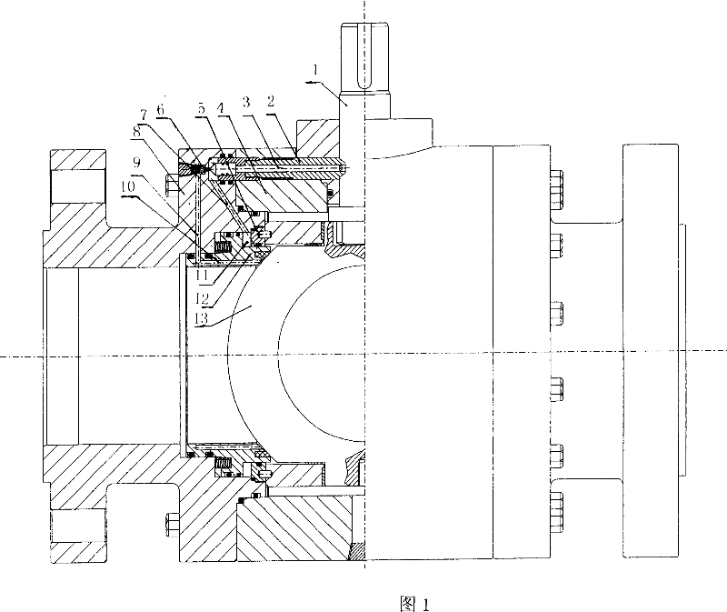
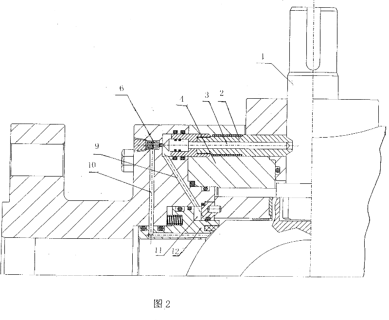
[0010] As shown in the figure, the present invention includes a valve body 4, a connecting body 8, a ball 13, a valve stem 1 and a valve seat 12, the valve seat 12 is provided with an oil storage chamber 11, and the oil storage chamber 11 is connected with the oil control device. The oil control device includes the ejector sleeve 2, the ejector rod 3 arranged in the ejector sleeve 2, the one-way valve 6 arranged in the connecting body 8, the oil inlet passage 9 and the oil outlet passage 7, and the valve seat 12 arranged in the Seat oil passage 10; the front part of the ejector sleeve 2 is located in the connecting body 8, the tail of the ejector sleeve 2 is located in the valve body 4, and the one-way valve 6 is on the top of the ejector rod 3; one end of the oil outlet passage 7 is connected to the oil storage The other end of the chamber 11 is connec...


PUM


Abstract

A ball valve without high-pressure torque is composed of valve body, connecting body, ball, valve rod and valve seat with an oil storage chamber communicated with oil controller. It has high sealing performance and is suitable for liquid delivering pipeline.

Description

technical field [0001] The invention relates to a ball valve, in particular to a torque-free ball valve under high pressure. Background technique [0002] The existing ball valves used on pipelines are usually provided with a worm gear device in order to save labor to open the ball valve, and the ball valve provided with such a worm gear device has a relatively high production cost. In addition, this kind of ball valve with worm gear device has high requirements on the ball due to wear between the valve seat and the ball, and its service life is relatively short. Contents of the invention [0003] The main purpose of the present invention is to design a torque-free ball valve under high pressure. [0004] The invention aims to solve the existing problems of high production cost and short service life of the existing ball valve with a worm gear device. [0005] The embodiment of the present invention is: it comprises valve body, con...

Claims


Application Information

Patent Timeline
Patent Type & Authority Patents(China)
IPC IPC(8): F16K5/06F16K5/20
Inventor 邱金全
Owner QFY HEAVY EQUIP CO LTD
Learn More