
Connector for connection boards

A technology of connectors and substrates, applied in the direction of electrical components, etc., can solve problems such as excessive labor and difficult setting, and achieve the effect of eliminating position offset

Inactive Publication Date: 2008-01-02
ALPS ALPINE CO LTD
View PDF2 Cites 0 Cited by
  • Summary
  • Abstract
  • Description
  • Claims
  • Application Information

AI Technical Summary

Problems solved by technology

[0009] However, in the above-mentioned existing connector structure for inter-board connection, there is a problem that a tapered extension must be provided at the front end portion of the female contact corresponding to the insertion angle of the male contact, and the tapered extension must be formed. , its setting is not easy and requires a lot of labor

Method used


Image

  • Connector for connection boards
  • Connector for connection boards
  • Connector for connection boards

Examples


Embodiment Construction

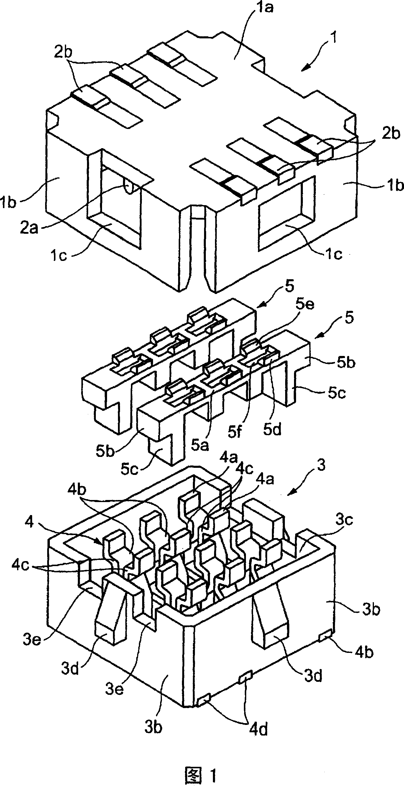
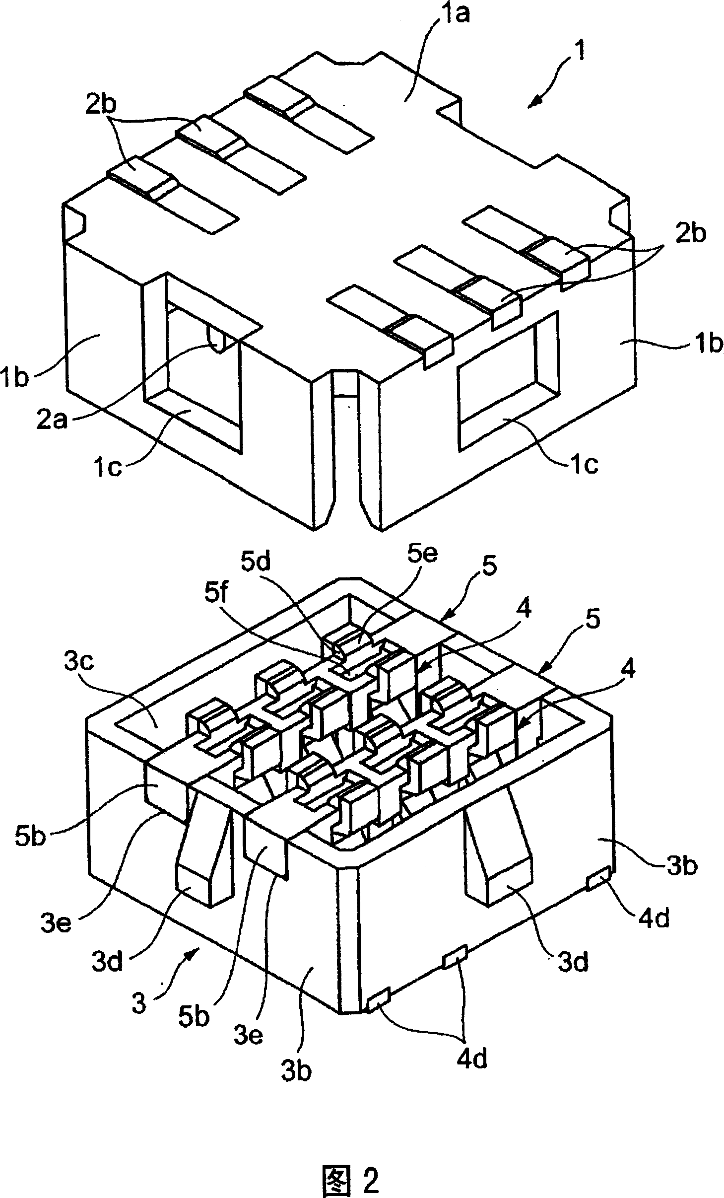
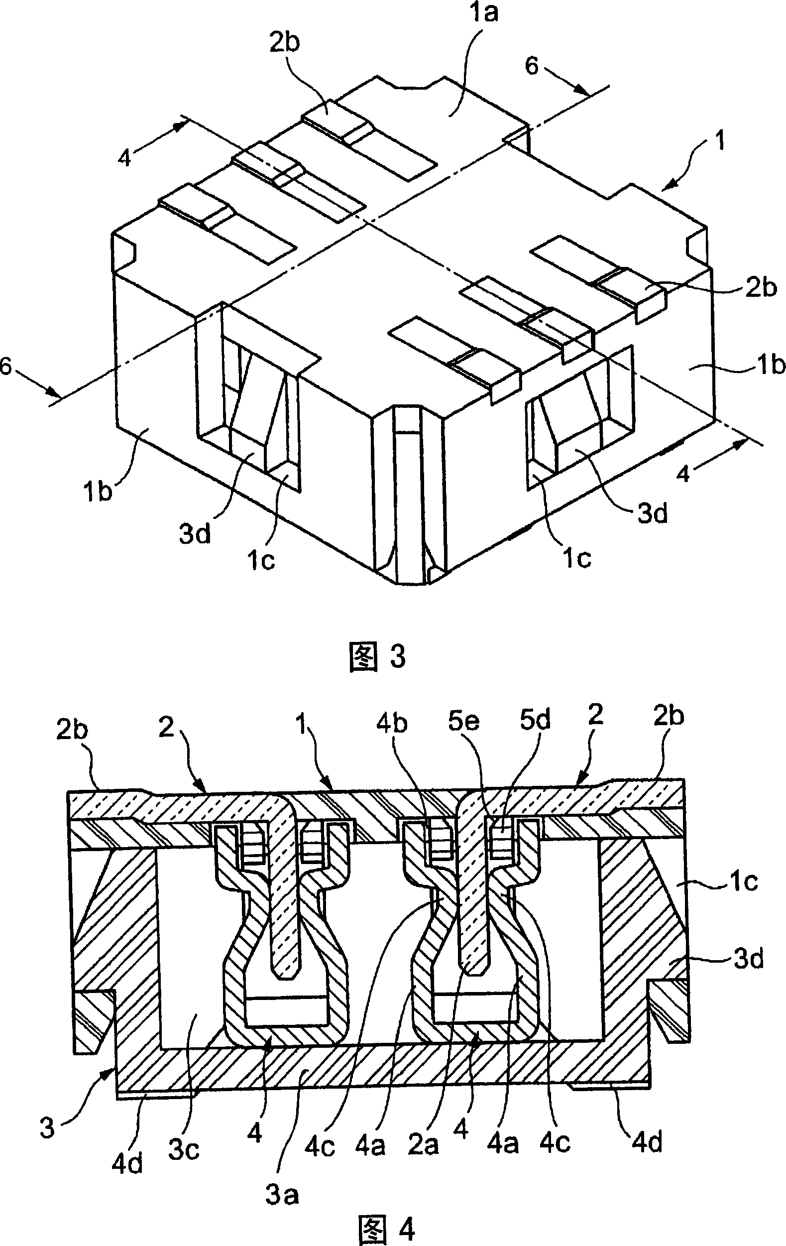
[0029] Next, FIGS. 1 to 7 show embodiments of a connector for connecting substrates according to the present invention. Fig. 1 is an exploded perspective view showing a connector for connecting between substrates of the present invention, Fig. 2 is an exploded perspective view showing the installation of a guide member of a connector for connecting between substrates of the present invention, Fig. 3 is an exploded perspective view showing the connector of the present invention The oblique view of the inventive connector used for the connection between substrates, Fig. 4 is a cross-sectional view of line 4-4 in Fig. 3, Fig. 5 is a cross-sectional view of Fig. 4 before combination, Fig. 6 is a line 6-6 in Fig. 3 Figure 7 is a cross-sectional view of Figure 6 before combination.

[0030] In the figure, the plug housing 1 is formed of an insulating material such as synthetic resin into a square box shape with an open bottom. The plug housing 1 has an upper plate 1a and four side ...


PUM


Abstract

PROBLEM TO BE SOLVED: To provide a connector for joining substrate which has simple structure and guides a contact terminal of to a joint of another contact terminal to perform their contact fit. ŽSOLUTION: The connector comprises a socket housing 3 to which a plastic case 1 having stick-shaped contact terminals 2 are attached, clip-shaped contact terminals 4 for contact fit to the stick-shaped contact terminals 2, guide members 5 which guide the stick-shaped contact terminals 2 to contact points 4c of the clip-shaped contact terminals 4. The guide member 5 has guides 5d with slopes 5c facing each other and extending toward the top and apertures 5f next to the guides 5d going through to the bottom. The contact points 4c of the clip-shaped contact terminals 4 are placed under the apertures 5f, and the guide members 5d are placed inside the tips of a pair of flexible tongues 4a of the clip-shaped contact terminals 4. Ž

Description

technical field [0001] The present invention relates to a connector structure for board-to-board connection used for circuit board-to-circuit board connection (board-to-board connection) of electronic equipment and the like. Background technique [0002] The existing connector structure used for connection between substrates is known to be composed of a male connector and a female connector. The male connector consists of a male-side connector housing and a plurality of male-type The female connector is composed of a female-side connector housing and a plurality of female-type terminals that are snapped together and have elastic tongues that are respectively in contact with each male-type terminal (for example, refer to Patent Document 1). [0003] Hereinafter, a conventional connector for connecting substrates will be described with reference to the drawings. [0004] FIG. 8 is a cross-sectional view showing a mating state of a male terminal and a female terminal of a conv...

Claims


Application Information

Patent Timeline
Patent Type & Authority Patents(China)
IPC IPC(8): H01R12/22H01R12/32
Inventor 我妻透佐藤一树川端隆志
Owner ALPS ALPINE CO LTD
Learn More