Supercharge Your Innovation With Domain-Expert AI Agents!

Vibration isolation table

一种隔离台、动基座的技术,应用在振动抑制调整、隔膜、减振器等方向,能够解决不能实现振动隔离台等问题

Inactive Publication Date: 2008-01-30
FUJIKURA COMPOSITES INC
View PDF10 Cites 0 Cited by
  • Summary
  • Abstract
  • Description
  • Claims
  • Application Information

AI Technical Summary

Problems solved by technology

However, such an improved vibration isolation table cannot be achieved simply by adjusting the length of the bottomed hollow cylinder and the length of the rocker

Method used


Image

  • Vibration isolation table
  • Vibration isolation table

Examples


Embodiment Construction

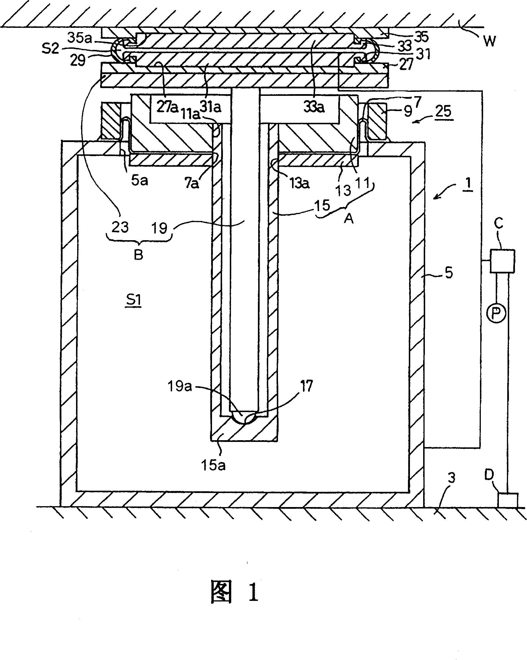
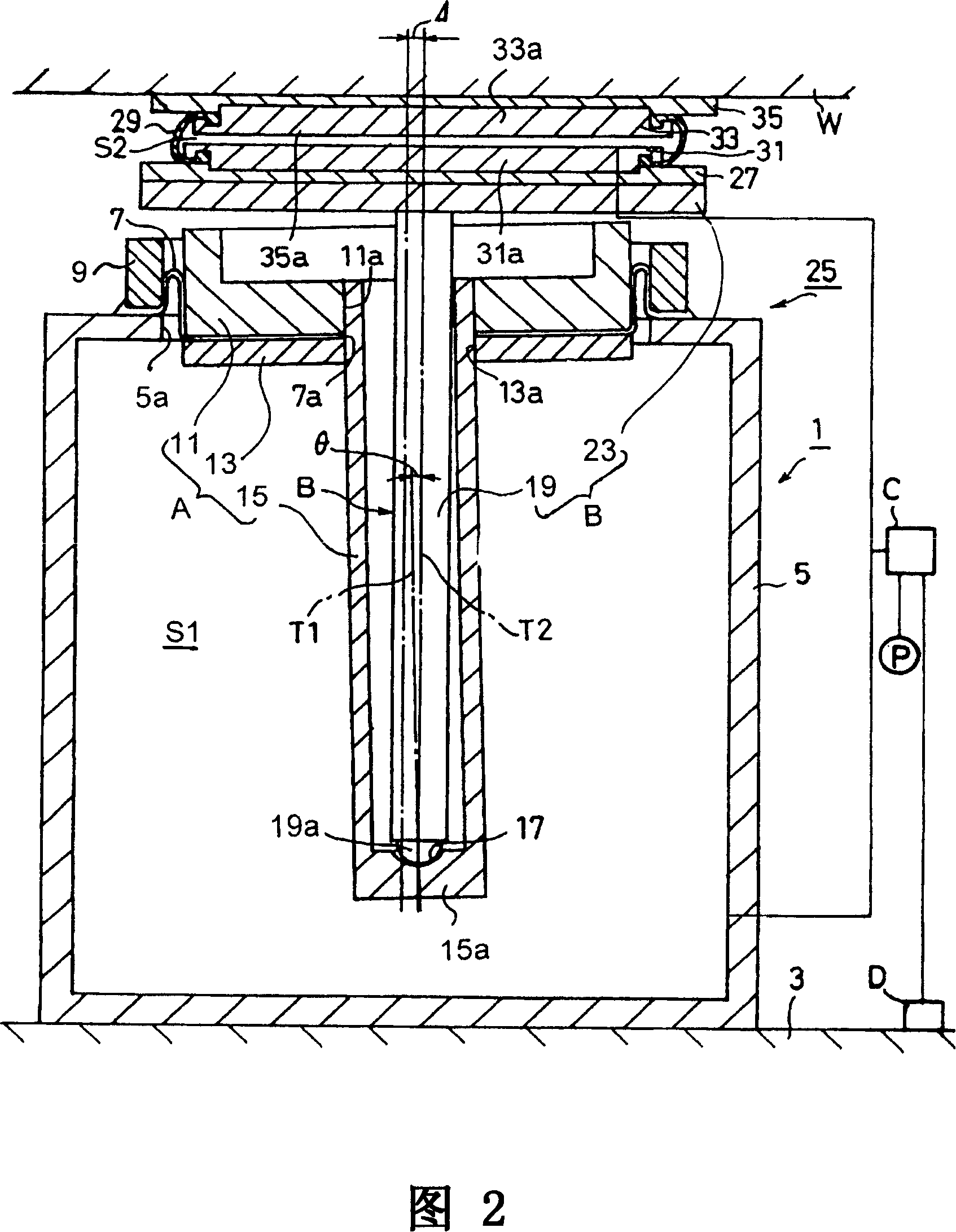
[0018] One embodiment of a vibration isolation table 1 incorporates a stationary housing 5, a diaphragm (a pressure-tight flexible member) 7, a stationary ring 9, and a primary movable base A. The vibration isolation table 1 is placed on the ground 3 so that a bottom surface of the fixed housing 5 touches the ground 3 . A circular opening 5a is provided on the top of the stationary case 5 . The diaphragm (undulating diaphragm) 7 closes the circular opening 5 a to form a first pressure chamber S1 in the stationary housing 5 . Specifically, the outer edge of the diaphragm 7 is hermetically held between an upper surface of the fixed housing 5 and the fixed ring 9 in an airtight manner, and the center of the diaphragm 7 is passed through a circle formed at the center of the diaphragm 7. The through hole 7a is fixed to the primary movable base A. As shown in FIG. The primary movable base A is composed of an annular piston 11 , an annular bottom plate 13 and a hollow cylindrical m...


PUM


Abstract

A vibration isolation table includes a stationary housing having an opening on top thereof; a pressure-tight flexible member which closes the opening to form a first pressure chamber in the stationary housing; a primary movable base which is coupled to a central portion of the pressure-tight flexible member, the primary movable base having a bottomed hollow cylindrical member; an intermediate movable base having a swingable rod which is inserted into the bottomed hollow cylindrical member so that a bottom end of the swingable rod is supported thereby to allow the swingable rod to swing with respect to the bottomed hollow cylindrical member; and a vibration-free base on which an object to be isolated from vibration is mounted, a second pressure chamber being formed between the intermediate movable base and the vibration-free base, the second pressure chamber being capable of expanding and contracting vertically.

Description

technical field [0001] This invention relates to a vibration isolating table for supporting objects, such as precision instruments, which are isolated from vibrations while isolating the objects from vibrations transmitted from the ground to the vibration isolating table, and more particularly to such a vibration isolating platform, its natural vibration frequency is smaller in the horizontal direction. Background technique [0002] As an example of a vibration isolating table used to prevent vibration from being transmitted from the ground to a precision instrument (for example, an optical stepper or an electron microscope) supported by the vibration isolating table, a vibration isolating table is known in the prior art, which It consists of a fixed shell, a pressure-tight flexible member (diaphragm), a primary movable base, a bottomed hollow cylinder and a vibration-free base. The stationary housing has an opening at its top. The pressure-tight flexible member is positio...

Claims


Application Information

Patent Timeline
Patent Type & Authority Patents(China)
IPC IPC(8): F16F15/023F16F7/00F16J3/02F16F15/027F16J3/04
CPCF16F15/0275F16F2230/14
Inventor 海沼正邦青树寿一玉置惠司植松克夫藤田知正珍田宽林明宏
Owner FUJIKURA COMPOSITES INC
Features
  • R&D
  • Intellectual Property
  • Life Sciences
  • Materials
  • Tech Scout
  • Unparalleled Data Quality
  • Higher Quality Content
  • 60% Fewer Hallucinations
Learn More