Crystal acceleration oscillation circuit

An oscillation circuit and crystal technology, applied in power oscillators, electrical components, etc., can solve the problem of crystal oscillation circuit not oscillating

Inactive Publication Date: 2008-08-27
SUNPLUS TECH CO LTD
View PDF3 Cites 1 Cited by
  • Summary
  • Abstract
  • Description
  • Claims
  • Application Information

AI Technical Summary

Problems solved by technology

[0005] The aforesaid improved crystal accelerated oscillator circuit cone can achieve the purpose of fast start-up by connecting multiple inverting amplifiers 11 in parallel. However, after starting the oscillation, since only one basic inverting amplifier 11 is reserved, the The crystal oscillator circuit is still the same as the traditional crystal oscillator circuit. Due to the changes in the operating voltage, process parameters, and load capacitance, the crystal oscillator circuit will not oscillate.

Method used


Image

  • Crystal acceleration oscillation circuit
  • Crystal acceleration oscillation circuit
  • Crystal acceleration oscillation circuit

Examples


Embodiment Construction

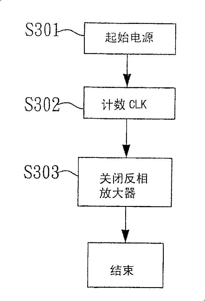
[0017] In order to better understand the technical content of the present invention, preferred specific embodiments are given as follows.

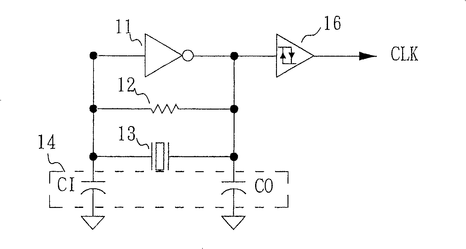
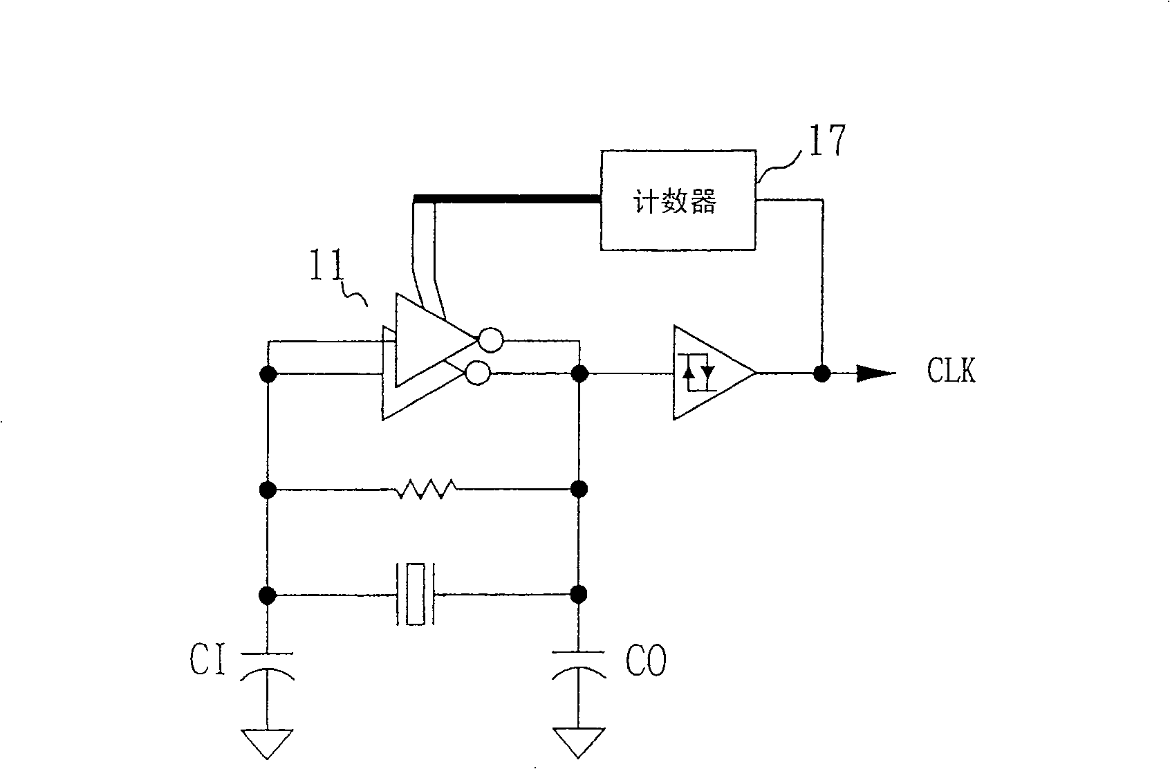
[0018] Figure 4 It is an embodiment of the crystal acceleration oscillation circuit of the present invention, which includes an amplifier group 41, a feedback resistor 42, a quartz oscillator crystal 43, a group of capacitor pairs 44, a first trigger 46, and a second trigger 47, and an amplifier switching logic 48. Wherein, the amplifier group 41 includes a plurality of parallel amplifiers 411 for signal amplification to provide the overall crystal oscillator circuit signal gain (Gain), these amplifiers 411 are preferably inverting amplifiers; the feedback resistor 42 is connected across The amplifier group 41 is used to establish a DC operating bias (Direct current operation bias) of the amplifier group; the quartz oscillator crystal 43 is connected across the feedback resistor 42 and the amplifier group 41 to generate a resonance (reso...


PUM


Abstract

This invention relates to a crystal acceleration oscillation circuit including a quartz oscillation crystal generating an oscillation single, an amplifier set, a feedback circuit, a first and a second trigger and an amplifier logic switch. The amplifier set amplifies the oscillation signal, the feedback resistor is for setting up DC working bias of said amplifier set, the input end of the first trigger is connected with the output end of said amplifier set, so the at, the amplifier signal triggers said first trigger to generate a first clock output, the input end of the second trigger is connected with the output end of said amplifier set, so its oscillation signal triggers a second trigger to generate a second clock output which has a retarding voltage greater than a preset value, the amplifier switch is connected with the second trigger to reduce intensity.

Description

technical field [0001] The invention relates to a crystal oscillation circuit, especially to a crystal acceleration oscillation circuit capable of ensuring oscillation Background technique [0002] figure 1 A traditional crystal oscillator circuit (Crystal Oscillator) is shown, which includes an inverting amplifier 11, a feedback resistor 12, a quartz oscillator crystal 13, a set of capacitor pairs 14, and a Schmitt trigger 16, wherein the inverting The phase amplifier 11 is used for signal amplification to provide the overall crystal oscillator circuit signal gain (Gain). The Schmitt trigger 16 is triggered by the amplified signal generated by the inverting amplifier 11 to output the clock signal CLK. The feedback resistor 12 is used for Establish the DC operating bias of the inverting amplifier 11, the quartz oscillator crystal 13 is used to generate an oscillation signal with a resonance frequency, and the capacitor pair 14 is used to make the parallel resonance (Paralle...

Claims


Application Information

Patent Timeline
Patent Type & Authority Patents(China)
IPC IPC(8): H03B5/06
Inventor 林盟智
Owner SUNPLUS TECH CO LTD
Why Eureka
Try Eureka