Quasi-synchronous reluctance motor

A reluctance motor, quasi-synchronous technology, applied in the direction of electrical components, electromechanical devices, etc., can solve the problems of increasing the cost of the drive system and low power factor

Inactive Publication Date: 2006-05-10
阿特拉斯-欣德勒电梯有限公司
View PDF0 Cites 0 Cited by
  • Summary
  • Abstract
  • Description
  • Claims
  • Application Information

AI Technical Summary

Problems solved by technology

[0005] However, even if this motor can overcome the disadvantages of the prior art, there is still the problem that the specific disadvantage of th

Method used


Image

  • Quasi-synchronous reluctance motor
  • Quasi-synchronous reluctance motor
  • Quasi-synchronous reluctance motor

Examples


Embodiment Construction

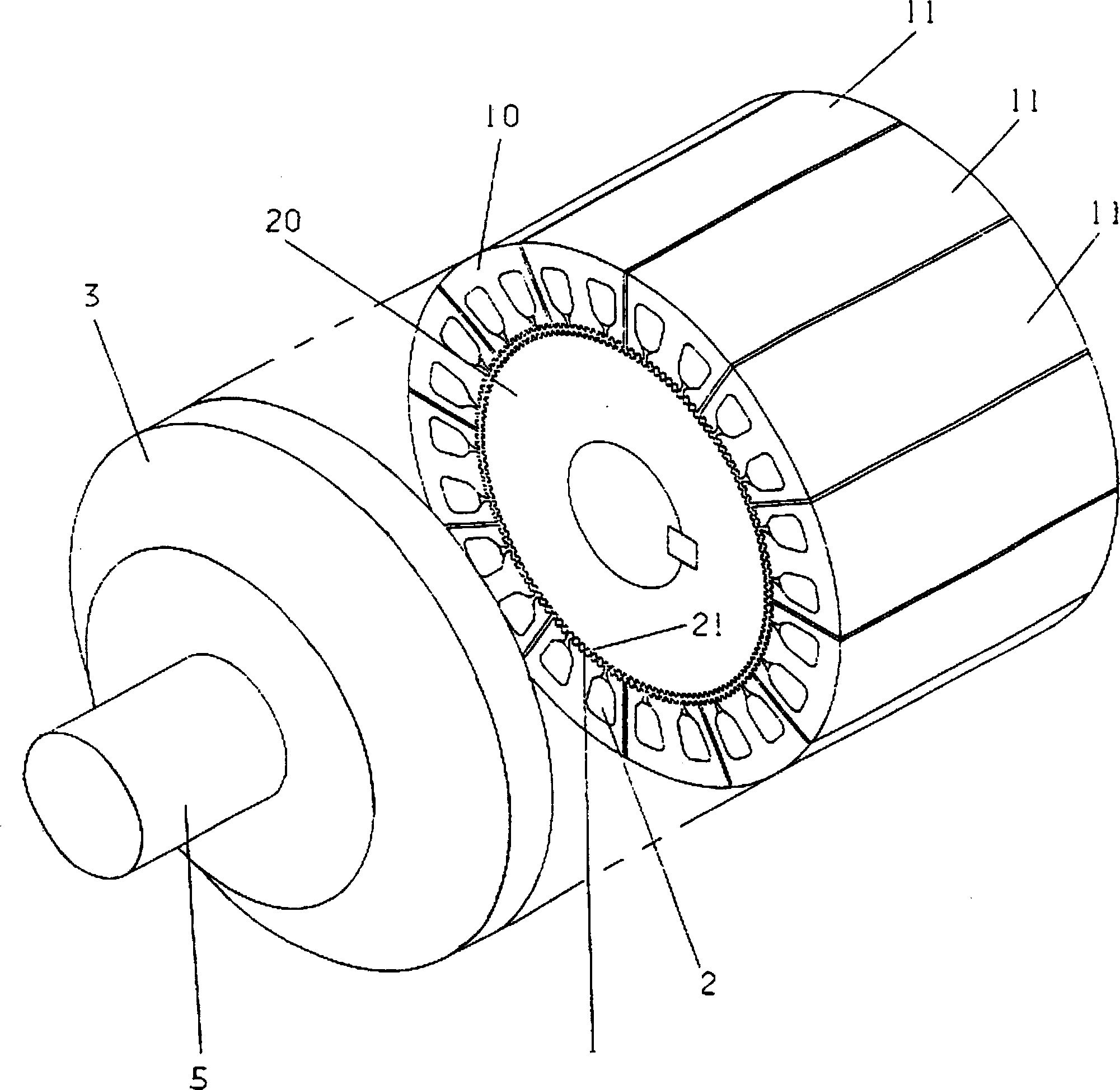
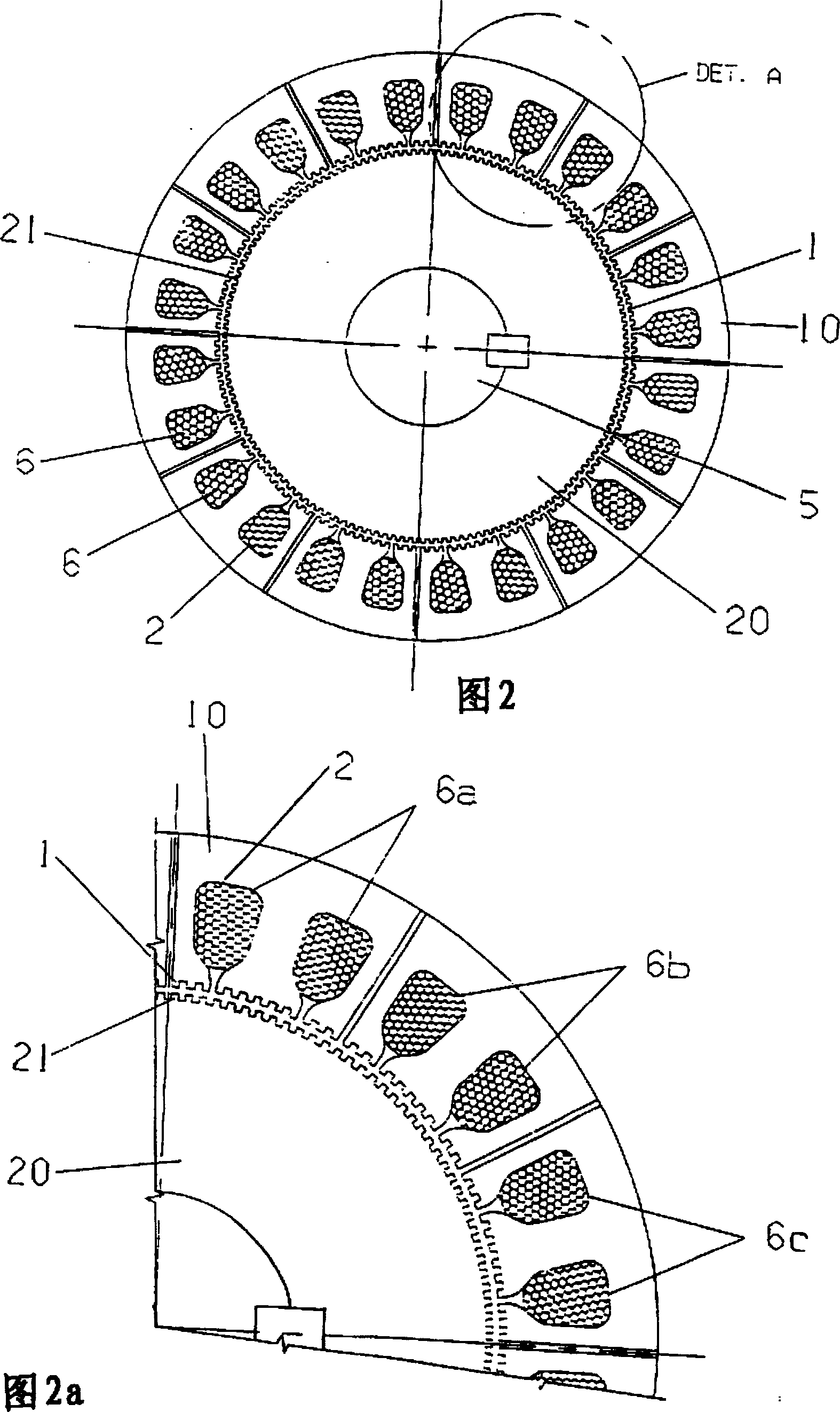
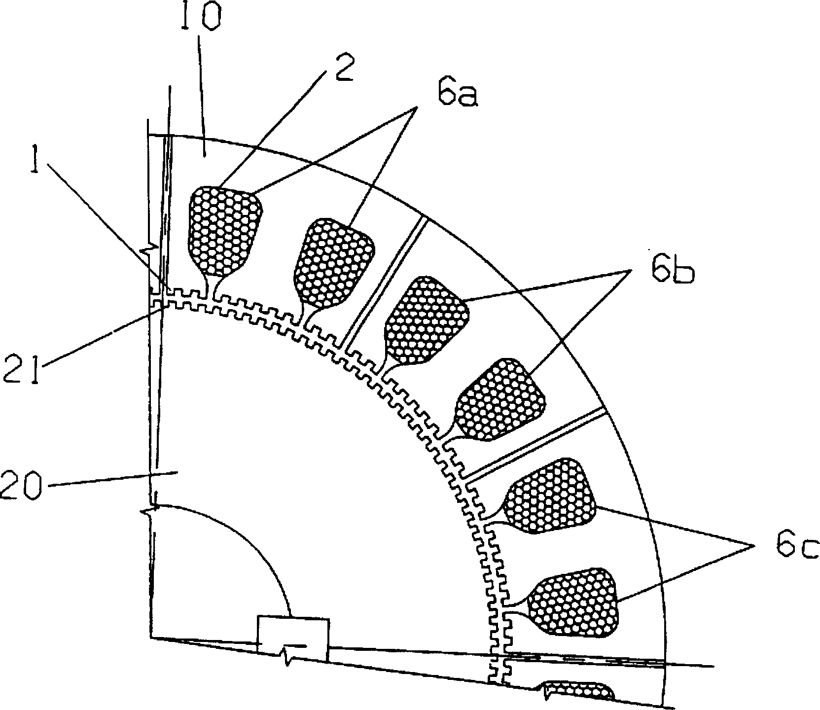
[0033] According to the above-mentioned drawings, the quasi-synchronous reluctance motor constituted according to the concept of the present invention is constructed according to such a stator 10, which has a ferromagnetic material sheet made of non-magnetic coupling or weak magnetic coupling A core consisting of segments 11 having longitudinal teeth 1 arranged on its surface facing said rotor 20 and slots 2 formed for accommodating one or more windings 6 .

[0034] These windings 6 comprise coils of magnetic material surrounding the stator 10 in order to generate a magnetic field when this winding is energized.

[0035] Since the integral part of the quasi-synchronous reluctance motor is the rotor 20, the rotor 20 also includes an iron core composed of some ferromagnetic material sheets, and longitudinal teeth 21 are evenly arranged along the end face turned to the stator 10. The teeth The number of 21 is different from the number of teeth 1 on the stator 10 .

[0036] more ...


PUM


Abstract

A quasi-synchronous reluctance machine defined by a stator having a core comprising an assembly of non-magnetically coupled or weakly coupled sectors of ferromagnetic material having in its A number of longitudinal teeth are arranged on the end face facing the rotor and slots are formed to accommodate the windings. The quasi-synchronous reluctance machine has said rotor as an integral part, the rotor also comprising a sheet core of ferromagnetic material formed with longitudinal teeth uniformly arranged on its end face facing the stator, said teeth having a number different from The number of teeth of the stator.

Description

technical field [0001] The present invention relates to a new type of reluctance motor, more specifically to a rotary or linear quasi-synchronous reluctance motor. Background technique [0002] As known to those skilled in the art, one of the best known and most widely used reluctance motors is the switched reluctance motor, which has limitations in its use due to the presence of torque and speed oscillations and the difficulty of implementing High current rate of change. [0003] A further disadvantage of such switched reluctance motors is that the circuitry used to control and power the reluctance motor is complex and expensive, especially for high power motors. [0004] As an alternative for solving the above-mentioned disadvantages, a patent application published on October 24, 1995 with the application number PI9400880-9 entitled "Reluctance motor is provided for a motor comprising a rotor and a stator. The stator Has a core consisting of sheets of magnetic material a...

Claims


Application Information

Patent Timeline
IPC IPC(8): H02K37/00H02K37/04
Inventor 法南多·加西亚
Owner 阿特拉斯-欣德勒电梯有限公司
Why Eureka
Try Eureka