High reliability power supply method for electric locomotive
A technology of electric locomotive and power supply method, which is applied in the field of rail transit, can solve the problems of lack of negative sequence and reactive current compensation capabilities, dead zone of electric locomotive power supply, large converter capacity, etc., to ensure switching power-off time, The effect of reducing reactive current and preventing power flow circulation
- Summary
- Abstract
- Description
- Claims
- Application Information
AI Technical Summary
Problems solved by technology
Method used
Image
Examples
Embodiment 1
[0037] A high-reliability power supply method for electric locomotives, including the following steps:
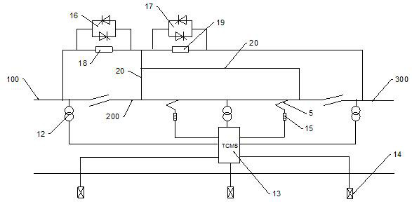
[0038] S1, by the switch 16 and the switch 16 in series with the impedance 18, switch 17 and the switch 2 17 in series with the impedance 2 19, located on the rail sensor 14 composed of a detection unit for the train relative to the catenary driving position and driving direction of the judgment, the neutral zone 200 no train running, switch 16 and switch 2 17 are disconnected, the train travels to the transition zone between the power supply arm 100 and the neutral zone 200, the switch 16 is closed, the train is within 200 of the neutral zone, Switch one 16 is disconnected, switch two 17 is closed, when the train leaves the transition zone between the neutral zone 200 and the power supply arm two 300, the switch two 17 is disconnected.
[0039] S2, the train by the catenary of the power supply arm 100 to the neutral zone 200 in the process of driving, by the power supply unit ...
Embodiment 2
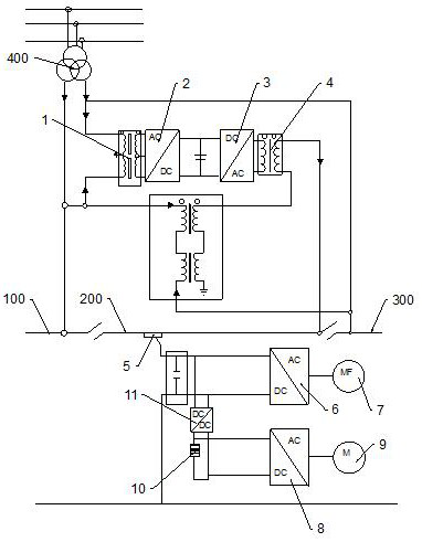
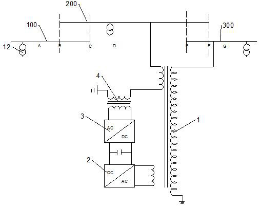
[0042] combine Figure 1 and Figure 2 , a high reliability power supply method for electric locomotives, comprising catenary and rail, the catenary comprises a neutral zone 200 and a power supply arm 100 and a power supply arm 200 and a power supply arm 300 at each end of the neutral zone 200, comprising a TCMS locomotive controller 13, a power supply unit and a detection unit.
[0043] The power supply unit comprises a traction transformer 400, a step-down transformer 1, a step-up transformer 4, a three-phase rectifier 2 and a single-phase inverter 3, the primary side output terminal of the step-down transformer 1 is connected to the power supply arm 100, the power supply arm 300 and the rail, the secondary side of the step-down transformer 1 is connected to the three-phase rectifier 2, the primary side of the step-up transformer 4 is connected to the AC output terminal of the single-phase inverter 3, the secondary side of the step-up transformer 4 is connected to the neutral regi...
Embodiment 3
[0050] combine Figure 1 , the output terminal of the current receiver 5 is connected to the traction inverter 8 and the auxiliary inverter 6, the output terminal of the auxiliary inverter 6 is connected to the load 7, the output of the traction inverter 8 is connected to the traction motor 9, the output terminal of the current receiver 5 is also connected to the battery 10 by the charger 11, the battery 10 is powered by the traction inverter 8 to the traction motor 9, the charger 11 is a DC / DC converter.
[0051] Through the battery to achieve the uninterrupted power supply of important loads, so that the locomotive in the no-power area when the load continues to work continuously, reduce the use of important load failure rate, improve the comfort of drivers and passengers, to ensure driving safety.
PUM
 Abstract
Description
Claims
Application Information
 - R&D
- Intellectual Property
- Life Sciences
- Materials
- Tech Scout
- Unparalleled Data Quality
- Higher Quality Content
- 60% Fewer Hallucinations
Browse by: Latest US Patents, China's latest patents, Technical Efficacy Thesaurus, Application Domain, Technology Topic, Popular Technical Reports.
© 2025 PatSnap. All rights reserved.Legal|Privacy policy|Modern Slavery Act Transparency Statement|Sitemap|About US| Contact US: help@patsnap.com


