
Control system, method and device for parallel connection of multiple battery subsystems

A control system and control device technology, applied in the direction of battery/fuel cell control device, battery circuit device, arrangement of multiple synchronous batteries, etc., can solve problems such as unfavorable maintenance, inability to cut off subsystems separately, damage, etc.

Inactive Publication Date: 2020-12-04
桑顿新能源科技(长沙)有限公司
View PDF4 Cites 10 Cited by
  • Summary
  • Abstract
  • Description
  • Claims
  • Application Information

AI Technical Summary

Problems solved by technology

[0003] The existing technology mainly adopts the method of direct parallel connection of battery subsystems to improve the battery life of new energy vehicles. However, since the battery subsystem has no independently controlled switch, when the battery subsystem fails, the subsystem cannot be cut off separately, only the entire battery subsystem can be cut off. The battery system directly affects the use of new energy vehicles. At the same time, the failure of the battery subsystem will continue to expand the risk
In addition, there is a problem of voltage difference between battery subsystems connected in parallel. The battery subsystem with high voltage will charge the battery subsystem with low voltage to form a current circulation between the battery subsystems. Since the internal resistance of the battery itself is small, a large current will be formed. Large circulation, which will cause damage and damage to batteries and electrical components, and is also not conducive to after-sales maintenance

Method used


Image

  • Control system, method and device for parallel connection of multiple battery subsystems
  • Control system, method and device for parallel connection of multiple battery subsystems
  • Control system, method and device for parallel connection of multiple battery subsystems

Examples


Embodiment Construction

[0058] The following will clearly and completely describe the technical solutions in the embodiments of the present application with reference to the drawings in the embodiments of the present application. Obviously, the described embodiments are only some of the embodiments of the present application, not all of them. Based on the embodiments in this application, all other embodiments obtained by persons of ordinary skill in the art without making creative efforts belong to the protection scope of this application.

[0059] The core of the present application is to provide a control system and method for parallel connection of multiple battery subsystems.

[0060] In order to enable those skilled in the art to better understand the solution of the present application, the present application will be further described in detail below in conjunction with the drawings and specific implementation methods.

[0061] It should be noted that the types of the master switch and the sla...


PUM


Abstract

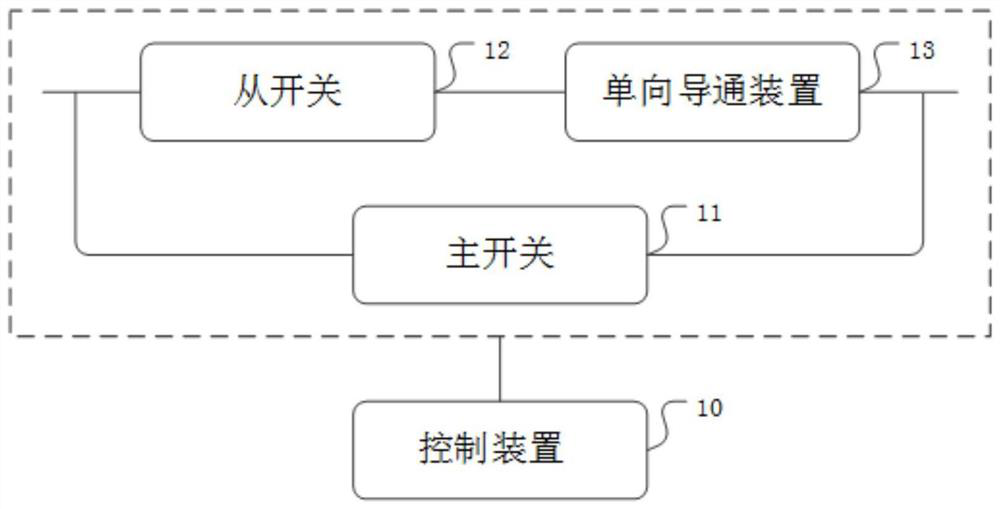
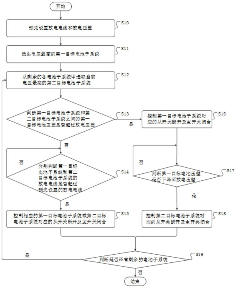
The invention discloses a control system, method and device for parallel connection of multiple battery subsystems, the control system comprises a control device, a main switch, a one-way conduction device and a slave switch which are arranged in each battery subsystem, and the slave switch and the one-way conduction device are connected in series and then are connected with the main switch in parallel. The control device is used for controlling the main switch and the slave switch corresponding to the target battery subsystem to be switched off when the target battery subsystem has a fault, and is also used for comparing the target battery voltage difference with a preset voltage difference according to the charging and discharging state and controlling the on-off of the main switch and the slave switch of the corresponding battery subsystem. Therefore, the voltage difference of the target battery is compared with the voltage difference, the voltage difference of the battery in the charging and discharging process can be actively balanced, and current circulation in the charging and discharging process of the battery is avoided. In addition, when the battery subsystem breaks down,the main switch and the slave switch are switched off, the broken-down battery can be cut off in time, the safety risk of the battery is reduced, and after-sales maintenance is facilitated.

Description

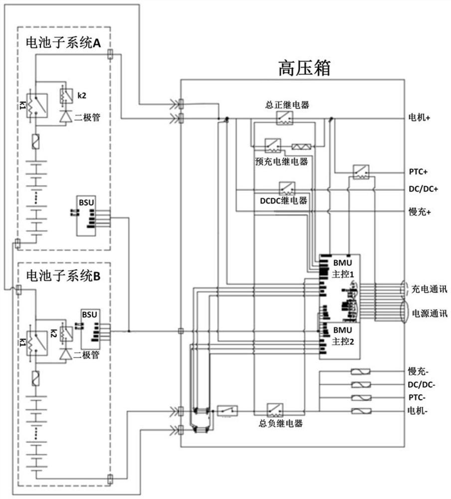
technical field [0001] The present application relates to the technical field of new energy vehicles, in particular to a control system, method and device for parallel connection of multiple battery subsystems. Background technique [0002] With the continuous development of science and technology, new energy vehicles are more and more popular among people. Since the endurance of new energy vehicles is closely related to the battery capacity of new energy vehicles, in order to be compatible with different high and low configuration models and increase the power of the battery system, many The battery system uses multiple battery subsystems in parallel. [0003] The existing technology mainly adopts the method of direct parallel connection of battery subsystems to improve the battery life of new energy vehicles. However, since the battery subsystem does not have an independently controlled switch, when the battery subsystem fails, the subsystem cannot be cut off individually,...

Claims


Application Information

Patent Timeline
IPC IPC(8): H02J7/00B60L58/18B60L58/22B60L58/20H01M10/42H01M10/44
CPCB60L58/18B60L58/20B60L58/22H01M10/4207H01M10/425H01M10/441H01M2010/4271H01M2220/20H02J7/0013H02J7/0019H02J7/0029H02J7/0031H02J7/0068Y02E60/10Y02T10/70
Inventor 黄磊徐强赵顺之
Owner 桑顿新能源科技(长沙)有限公司
Learn More