
A ground automatic phase separation device and its control method for partitions

A technology of automatic over-phase and zoning, applied in transportation and packaging, power lines, vehicle parts, etc., can solve the problems of high operation and maintenance costs, long switching time of mechanical switches, accelerated aging of main insulation, etc., to reduce operation and maintenance costs. , the effect of reducing the dead time of switching and preventing the circulation of the power flow

Active Publication Date: 2021-12-24
ZHUZHOU CSR TIMES ELECTRIC CO LTD
View PDF6 Cites 0 Cited by
  • Summary
  • Abstract
  • Description
  • Claims
  • Application Information

AI Technical Summary

Problems solved by technology

[0006] 1) It is impossible to accurately control the opening and closing phases, and the control is usually only accurate to ±0.5ms (4.5° of 50Hz AC), and the control to achieve this index is very complicated
[0007] 2) The switching time of the mechanical switch is long, which makes the neutral section have a long time without electricity, usually more than 130ms
[0008] 3) Vacuum circuit breakers have over-voltage and over-current impacts. The over-voltage is usually above 70kV, which will accelerate the aging of the main insulation of the high-voltage electrical equipment on the vehicle. Over-current impacts can also easily cause the locomotive to trip. Less than 60,000 times, regular maintenance and replacement are required, so the later operation and maintenance costs are high
[0010] Chinese patent application CN105799553A discloses an electronic ground automatic phase separation device, which uses a thyristor as the core device to realize power electronic ground conversion automatic phase separation, which can reduce the impact of overvoltage and overcurrent and improve the service life of high-voltage electrical equipment on the vehicle , but in this scheme, the two electronic switching valve group units between the two-phase power supply arm and the neutral section are directly connected to the central controller unit, and the central controller unit independently controls the two electronic switching valve group units. The two thyristors in an electronic switching valve group unit are controlled as a whole, that is, the two thyristors are controlled to be turned on or off at the same time, which can easily lead to misoperation and misconduct, the reliability is not high, and due to the traction There will be a phase angle error between the traction transformers on both sides of the power supply system partition, and there will be differences in the power and power factor of the loads on both sides, so there will be a large difference in the power supply voltage on both sides of the traction power supply system partition. When the electronic switching valve group units are turned on at the same time, the bilateral power supply connection will generate a power flow circulation, resulting in the malfunction of the overcurrent protection of the partition, and affecting the safety of the train over phase separation

Method used


Image

  • A ground automatic phase separation device and its control method for partitions
  • A ground automatic phase separation device and its control method for partitions
  • A ground automatic phase separation device and its control method for partitions

Examples


Embodiment 1

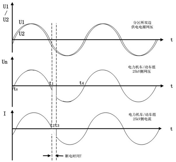
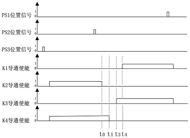
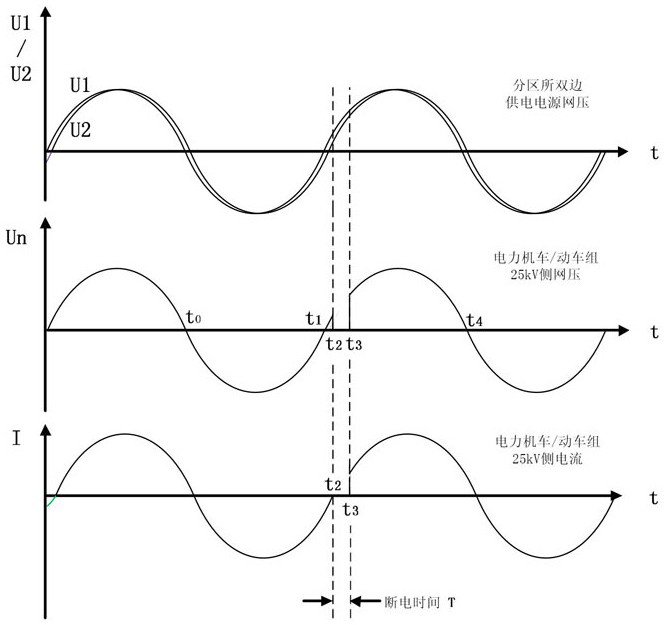
[0063] Such as figure 2 As shown, the ground automatic phase separation device used in the partition of this embodiment includes a control unit 1, a detection unit connected to the control unit 1, two thyristor valve group units 2, and the two thyristor valve group units 2 are located in the neutral zone and the partition. Between the power supply arms of the substation on both sides of the substation, that is, between the neutral zone and the power supply arm on one side, and between the neutral zone and the power supply arm on the other side, a thyristor valve group unit 2 is respectively arranged, and each thyristor valve group unit 2 It includes two thyristor valves connected in anti-parallel connection, each thyristor valve is connected to the control unit 1, when the train is over-phased, the detection unit detects the network pressure signal and the current signal of the two thyristor valve group unit 2, and sends them to the control unit 1, The control unit 1 generate...

Embodiment 2

[0083] Such as Figure 5 As shown, from left to right is forward driving, and from right to left is reverse driving. The thyristor valve group unit 2 of this embodiment specifically includes a thyristor valve connected between the power supply arm of the substation on the left side of the divisional substation and the neutral zone. K1, thyristor valve K3, and thyristor valve K2, thyristor valve K4, thyristor valve K1, thyristor valve K3, thyristor valve K2, and thyristor valve K4 connected between the neutral zone and the power supply arm of the substation on the right side of the district substation are respectively connected with the control The unit 1 is connected, and the control unit 1 generates control signals and sends them to the thyristor valve K1, the thyristor valve K3, the thyristor valve K2, and the thyristor valve K4 to control on-off. By controlling the on-off of thyristor valve K1, thyristor valve K3, thyristor valve K2, and thyristor valve K4 independently thr...


PUM


Abstract

The invention discloses a ground automatic phase separation device and a control method for partitions. The device includes a control unit, a detection unit respectively connected to the control unit, and two thyristor valve group units. The two thyristor valve group units are respectively arranged in the neutral zone and Between the power supply arms of the substations on both sides, each thyristor valve group unit includes two thyristor valves connected in anti-parallel connection, and each thyristor valve is connected to the control unit. The current signal of the thyristor valve group unit is sent to the control unit, and the control unit generates control signals and sends them to each thyristor valve to control on-off; this method is the control method of the above-mentioned device. The invention has the advantages of simple control, high control precision, high safety and reliability, short power-off time when over-phase splitting occurs, and can avoid power flow circulation between bilateral power supplies of partitioned stations.

Description

technical field [0001] The invention relates to the technical field of over-phase separation in traction power supply systems of electrified railways, in particular to a ground automatic over-phase separation device for partitions and a control method thereof. Background technique [0002] Such as figure 1 As shown, the electrified railway traction power supply system adopts 27.5kV single-phase power supply mode, and the traction substation converts the 110kV or 220kV three-phase power provided by the power system into 27.5kV single-phase AC power for the traction power supply network, but single-phase power supply is easy Negative sequence currents are generated in the power grid, and negative sequence currents will have a great impact on equipment, transmission lines, relay protection, etc. in the power grid; in order to balance the A, B, and C three-phase currents of the power system, traction substations The catenary adopts phase-commutation and alternating power supply...

Claims


Application Information

Patent Timeline
Patent Type & Authority Patents(China)
IPC IPC(8): B60M3/04
Inventor 吕顺凯胡家喜张志学邱文俊周方圆曹洋吴明水仇乐兵周靖王智成龚芬胡前刘永丽杨磊宁佐友
Owner ZHUZHOU CSR TIMES ELECTRIC CO LTD
Learn More