Supercharge Your Innovation With Domain-Expert AI Agents!

Disposable syringe

A disposable and syringe technology, applied in the direction of infusion sets, syringes, etc., can solve the problem of not being able to withdraw the needle body

Inactive Publication Date: 2008-10-22
许 明正 +2
View PDF4 Cites 0 Cited by
  • Summary
  • Abstract
  • Description
  • Claims
  • Application Information

AI Technical Summary

Problems solved by technology

And the most important thing is, according to its icon structure and operation schematic diagram, when the arrow shaft 16 is solidified with the needle base 13 by the arrow 162, it will be blocked by the closed end 111 of the needle cylinder 11 and cannot continue to move forward. Therefore, if you continue to push and push The rod 15 tries to release the locking function between the arrow seat 161 and the clamping ring 151, hoping to use the compression spring 17 to release the elastic recovery force to withdraw the needle seat 13, but the situation where the straight line L on the icon passes through the clamping ring 151 is not ugly. It can be seen that the clamping ring 151 with a slope and a reduced diameter will obviously block the movement of the arrow shaft 16, the arrow seat 161 and the needle seat 13, so that the arrow shaft 16 and the compression spring 17 will fail and the needle body 14 cannot be retracted.

Method used


Image

  • Disposable syringe
  • Disposable syringe
  • Disposable syringe

Examples


Embodiment Construction

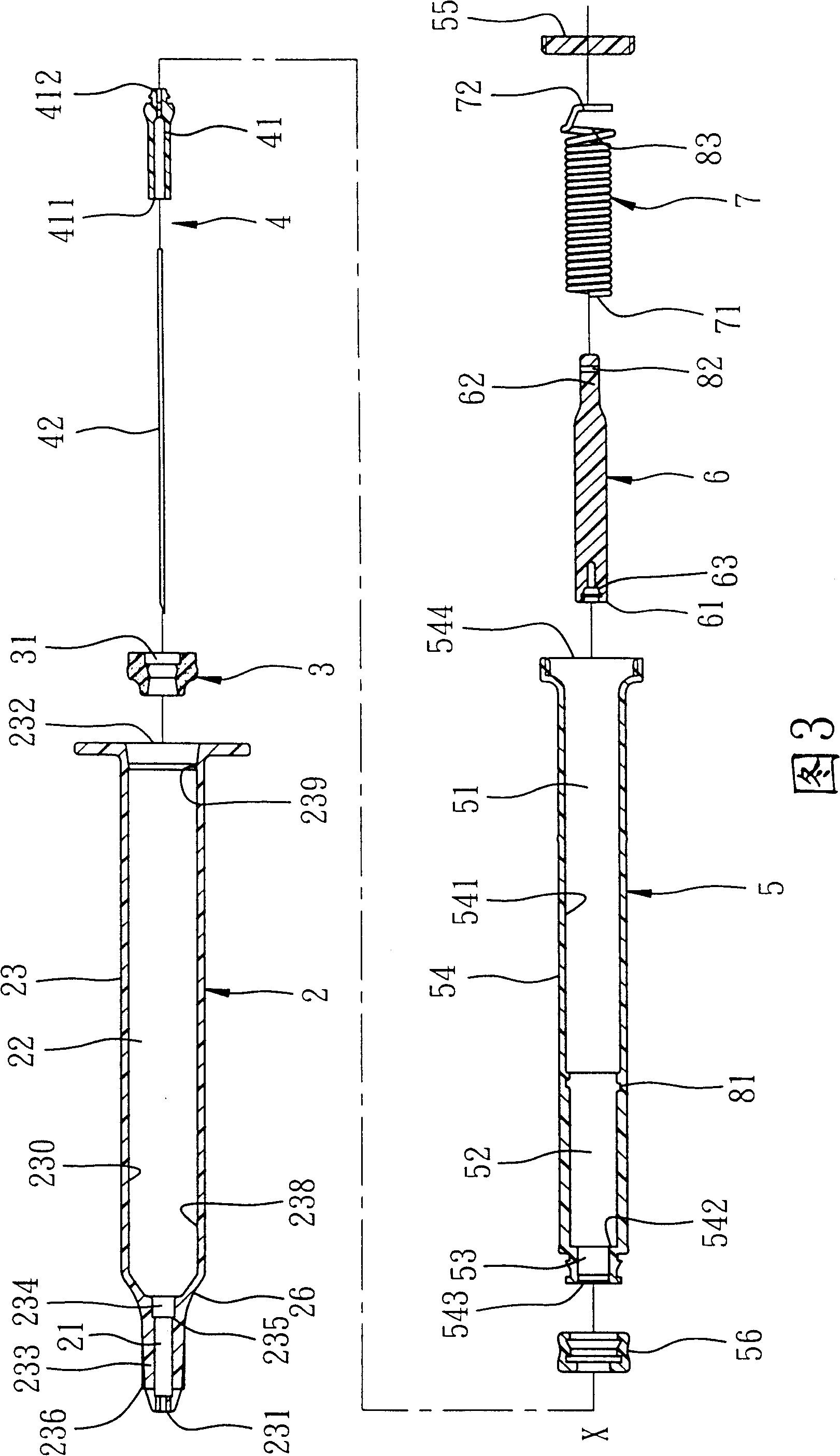
[0061] As shown in Figure 3 and Figure 4, the first preferred embodiment of the disposable syringe of the present invention includes a syringe body 2, a positioning seat 3, a needle set 4, a push rod 5, an arrow pin 6, and a compression spring 7 and a limit piece 8.

[0062] The syringe body 2 has a tube wall 23 surrounding an axis X and defining a small-diameter section 21 and a large-diameter section 22 . The pipe wall 23 has an outlet end 231 adjacent to the small aperture section 21, an inlet end 232 adjacent to the large aperture section 22, an annular groove 234 formed on an inner surface 230 and extending from the large aperture section 22 toward the small aperture section 21 , a shoulder 235 defined between the small aperture section 21 and the annular groove 234, a positioning protrusion ring 238 formed on the inner surface 230 of the large aperture section 22 and adjacent to the small aperture section 21, and a positioning protrusion ring 238 formed on the inner surf...


PUM


Abstract

A disposable injector is composed of a main body consisting of a small-diameter segment and a big-diameter segment which has an outlet, an inlet, a ring slot and a shoulder, a needle set consisting of needle seat jammed in said ring slot and needle, a push rod, an arrowhead bolt, a compression spring and a position limiter. After said arrowhead bolt is matched with said needle set, the compression spring can draw it along with the needle set back in push rod.

Description

【Technical field】 [0001] The invention relates to a disposable syringe, in particular to a disposable syringe capable of accommodating a hidden needle body. 【Background technique】 [0002] Referring to Fig. 1, taking U.S. Patent No. 5,211,628 as an example, it mainly includes a hollow syringe 11, a positioning seat 12, a needle seat 13, a needle body 14, a push rod 15, an arrow shaft 16, and a Spring 17 in compressed state. [0003] The barrel 11 has a closed end 111 , and a needle hole 112 passing through the closed end 111 and extending along an axis X. As shown in FIG. [0004] The positioning seat 12 is forced into the barrel 11 and leans against the closed end 111 , and has a retaining ring 121 surrounding the axis X that can be stretched and contracted. [0005] The needle seat 13 penetrates the positioning seat 12 along the axis X, and has a fastening hole 131 penetrating along the axis X, and a protrusion 133 extending along the axis X and forming an annular gap 13...

Claims


Application Information

Patent Timeline
Patent Type & Authority Patents(China)
IPC IPC(8): A61M5/31
Inventor 许明正黄明敏许沛扬
Owner 许 明正
Features
  • R&D
  • Intellectual Property
  • Life Sciences
  • Materials
  • Tech Scout
  • Unparalleled Data Quality
  • Higher Quality Content
  • 60% Fewer Hallucinations
Learn More