Puncture instrument for punctured high frequency treatments

Inactive Publication Date: 2001-03-13
FUJI PHOTO OPTICAL CO LTD
View PDF10 Cites 152 Cited by
  • Summary
  • Abstract
  • Description
  • Claims
  • Application Information

AI Technical Summary

Problems solved by technology

In this connection, conventional instruments designed for high frequency therapeutic treatments within an intracavitary tract, for example, are unable to treat cancer cells or other diseased portions which exist underneath the mucous membrane.
On the other hand, conventional punctur

Method used


Image

  • Puncture instrument for punctured high frequency treatments
  • Puncture instrument for punctured high frequency treatments
  • Puncture instrument for punctured high frequency treatments

Examples


first embodiment

Referring now to FIG. 7, there is shown a further embodiment of the invention, employing a puncture instrument 40 which is the same as the foregoing embodiment in that it has a puncture needle member 42 slidably fitted in a flexible guide tube 41 of electrically insulating material. The puncture needle member 42 is constituted by an elongated flexible needle body 42a, a sharp-pointed needle head 42b which is contiguously provided at the fore end of the flexible needle body 42a, and a high frequency electrode 43 which is integrally embedded in the puncture needle member 42, with a pointed end of an acicular electrode portion 43a exposed to the outside on a lateral side of the puncture needle member 42 at a position close to the needle head 42b. A wiring cable 44 from the high frequency electrode 43 is passed through the flexible needle body 42a of the puncture needle member 42 and connected at its proximal end to a high frequency power source in the same manner as in the above-descri...

second embodiment

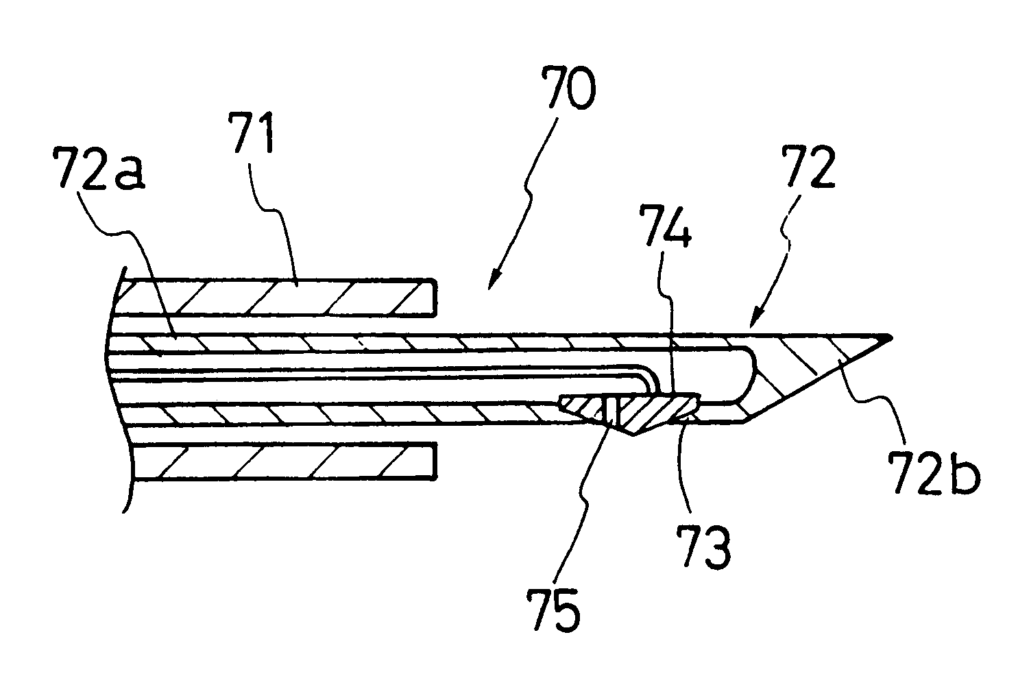
Shown in FIG. 8 is a further embodiment of the invention, employing a puncture instrument 50 which is constituted by a guide tube 51 of an electrically insulating material and a puncture needle member 52 similarly of an electrically insulating material. The puncture needle member 52 is provided with a sharp-pointed needle head 52b at the fore end of a hollow tubular needle body 52a. A window 53 is opened in the hollow tubular body 52a of the puncture needle member 52 at a position close to the proximal end of the sharp-pointed needle head 52b, receiving therein a high frequency electrode 54 in such a manner as to expose an acicular electrode portion 54a through the window 53. A wiring cable 55 from the high frequency electrode 54 is passed through the hollow tubular body 52a of the puncture needle member 52. The puncture instrument of this construction is also capable of applying a high frequency treatment to a broader range of areas around the puncture needle member similarly to th...

third embodiment

Shown in FIG. 4 is a further embodiment of the invention, employing a puncture instrument 60 which is constituted by a guide tube 61 and a puncture needle member 62 similarly to FIG. 8. The puncture needle member 62 is provided with a sharp-pointed needle head 62b at the fore end of a hollow tubular body 62a. A window 63 is opened on a lateral side of the tubular needle body 62a at a position close to the proximal end of the sharp-pointed needle head 62b. In this case, however, in order to use the inner hollow space of the tubular body 62a of the needle member 62 as a suctional passage, a high frequency electrode 64 with an acicular electrode portion 64a is securely fixed on the inner periphery of the tubular needle body 62a along one side thereof. The acicular electrode portion 64a is located in the window 63 in such a manner as to leave a gap space 65 therein to communicate the suctional passage in the tubular body 62a of the puncture member 62 with the outside.

The puncture needle...


PUM


Abstract

A puncture instrument capable of punctured high frequency treatments. The puncture instrument essentially includes: a guide tube to be inserted into an intracavitary portion of a patient; a puncture needle member having an elongated needle body slidably received in the guide tube, and a sharp-pointed needle head provided contiguously at the fore end of the elongated needle body and protrudable out of the guide tube to penetrate into a target intracorporeal portion to be treated when the needle body is manipulated in a forward direction; and a high frequency electrode provided on a fore end portion of the needle body to be penetrated into the target intracorporeal portion together with the sharp-pointed needle head.

Description

1. Field of the ArtThis invention relates generally to a medical puncture instrument, and more particularly to a puncture instrument for punctured high frequency treatments, having a high frequency electrode on a puncture needle member to be driven into a target organ or tissues in an intracorporeal region of a patient for a high frequency treatment.2. Description of the Prior ArtFor instance, ultrasound endoscopes are widely resorted to in the medical fields not only for intracorporeal examinations and diagnosis but also for therapeutic purposes to give an appropriate treatment to a diseased portion on the basis of the results of an examination or diagnostic observation. In many cases, the ultrasound endoscopes of this sort are provided with an ultrasound imaging means along with an endoscopic observation means at the fore end of a catheter-like insert portion to be introduced into an intracavitary portion of a patient. The endoscopic observation means is suitable for examinations ...

Claims


Application Information

Patent Timeline
IPC IPC(8): A61B18/14A61B18/00A61B18/12A61B19/00
CPCA61B18/1477A61B10/02A61B19/5202A61B2018/0022A61B2018/00482A61B2018/00553A61B2018/00982A61B2019/5278A61B2218/007A61B2090/3782A61B90/30
Inventor ABE, KENJIKONDO, MITUO
Owner FUJI PHOTO OPTICAL CO LTD
Why Eureka
Try Eureka