Stent loading tool and method for use thereof

a technology for loading tools and stents, applied in the field of stent loading tools, can solve the problems of inability to deliver stents in a collapsed or compressed state, stents must be handled with great care, and the material making up stents is easily deformed, so as to achieve a simple and reliable manner

Active Publication Date: 2009-02-26
MEDTRONIC VENTOR TECH
View PDF101 Cites 449 Cited by
  • Summary
  • Abstract
  • Description
  • Claims
  • Application Information

AI Technical Summary

Benefits of technology

[0012]Accordingly, it is a broad object of the present invention to overcome the above-mentioned disadvantages and limitations of the prior art and provide a loading tool suitable for extracting a stent-mounted valve from its packaging, crimping that stent-mounted valve into a profile suitable for introduction into a catheter delivery tube, and loading that stent mounted valve into a catheter delivery tube in a simple and reliable manner.
[0014]The described loading tool may be used for withdrawing, crimping, and loading a stent-mounted valve into a catheter delivery tube, and further for facilitating pushing of the stent-mounted valve from the catheter delivery tube into a native heart valve orifice.
[0022]The loading tool may then be attached to a control and delivery member, e.g., a inner shaft of a catheter delivery tube, and then both the loading tool and the stent-mounted valve are drawn into the catheter delivery tube. This loading tool design greatly increases the ease of transfer of the valve from the storage device to the catheter delivery tube. Also, with this loading tool, the valve is subjected to minimal handling during transfer into the catheter delivery tube, a feature which assures the integrity of the valve itself.
[0044]Although the described device is described with reference to a stent-mounted valve, the loading tool may be readily adapted for use with any bio-prosthetic device which is switched from a substantially open state to a substantially closed state in order to load into a catheter delivery tube.
[0045]The described loading tool need not be disconnected from the stent-mounted valve prior to delivery, as required by prior art tools and methods. Instead, the loading tool itself becomes part of the delivery system and facilitates the release of the stent-mounted valve out of the catheter delivery tube when the implantation site is reached.

Problems solved by technology

However, since the stent-mounted prosthetic valve has leaflets of pericardium material, it cannot be delivered to the hospital or medical facility in a collapsed or compressed state.
Since the material making up the stent is easily deformed or damaged, the stent must be handled with great care.
The step of collapsing the stent is a delicate process and, if not performed properly, may cause delay the implantation procedure or may entail excessive handling of the stent or even damage to the valve.
Removal of the stent from the glutaraldehyde liquid medium in the storage and delivery container by surgically-gloved surgical personnel may be awkward.
A drawback to this procedure is that the step of threading the filaments through the valve can be a tedious and time-consuming process.
Also, since the filaments have no purpose after the crimping step, they must be removed from the implant prior to the delivery procedure.
Removal of the filaments may cause damage to the valve and may even partially undo the crimping step.
None of these patents or patent applications show the device and procedures described further hereinbelow, nor do they satisfactorily solve the problems which have been described above relating to transfer of the valve from a storage device, in which the valve is in an expanded state, to the delivery tool, in which the valve is in a substantially compressed state.

Method used


Image

  • Stent loading tool and method for use thereof
  • Stent loading tool and method for use thereof
  • Stent loading tool and method for use thereof

Examples


Embodiment Construction

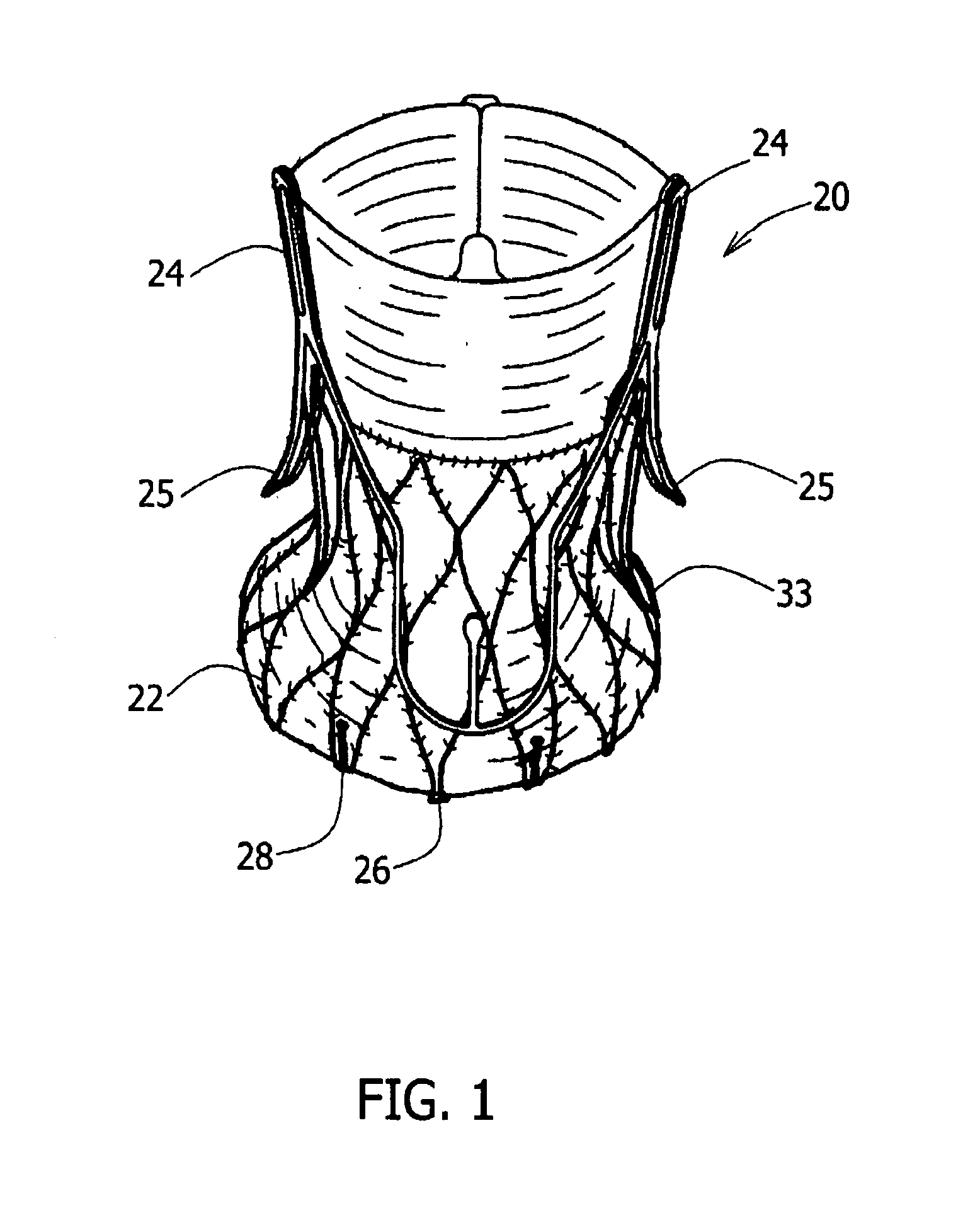
[0061]FIG. 1 is a perspective view of a self-expanding stent-mounted valve (20). Stent-mounted valve (20) may be of several types as is known to those skilled in the art, but in the example of FIG. 1, the stent-mounted valve (20) is shown as a wire structure having a wire-mesh, expandable frame stent (22). Engagement arms (25) are typically configured to engage and / or rest against floors of aortic sinuses, to position the prosthetic valve assembly (20) in the native valve, and to apply an axial force directed towards the left ventricle. A more detailed description of our basic stent-mounted valve is provided in U.S. patent application Ser. No. 11 / 024,908, filed Dec. 30, 2004, published as No. 2006 / 0149360, to Schwammenthal, et al., herein incorporated by reference in its entirety.

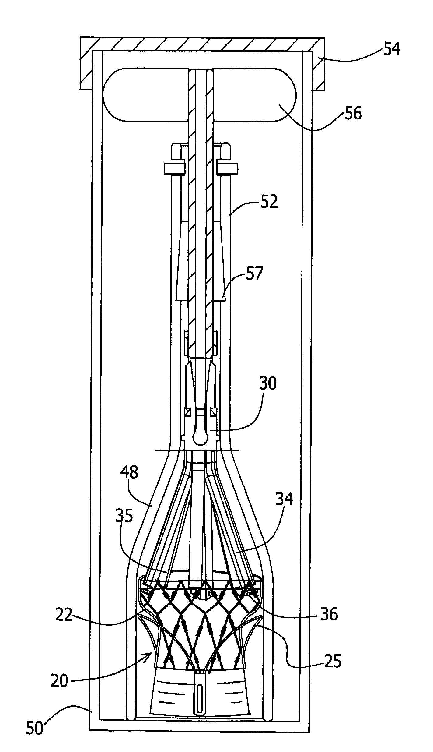
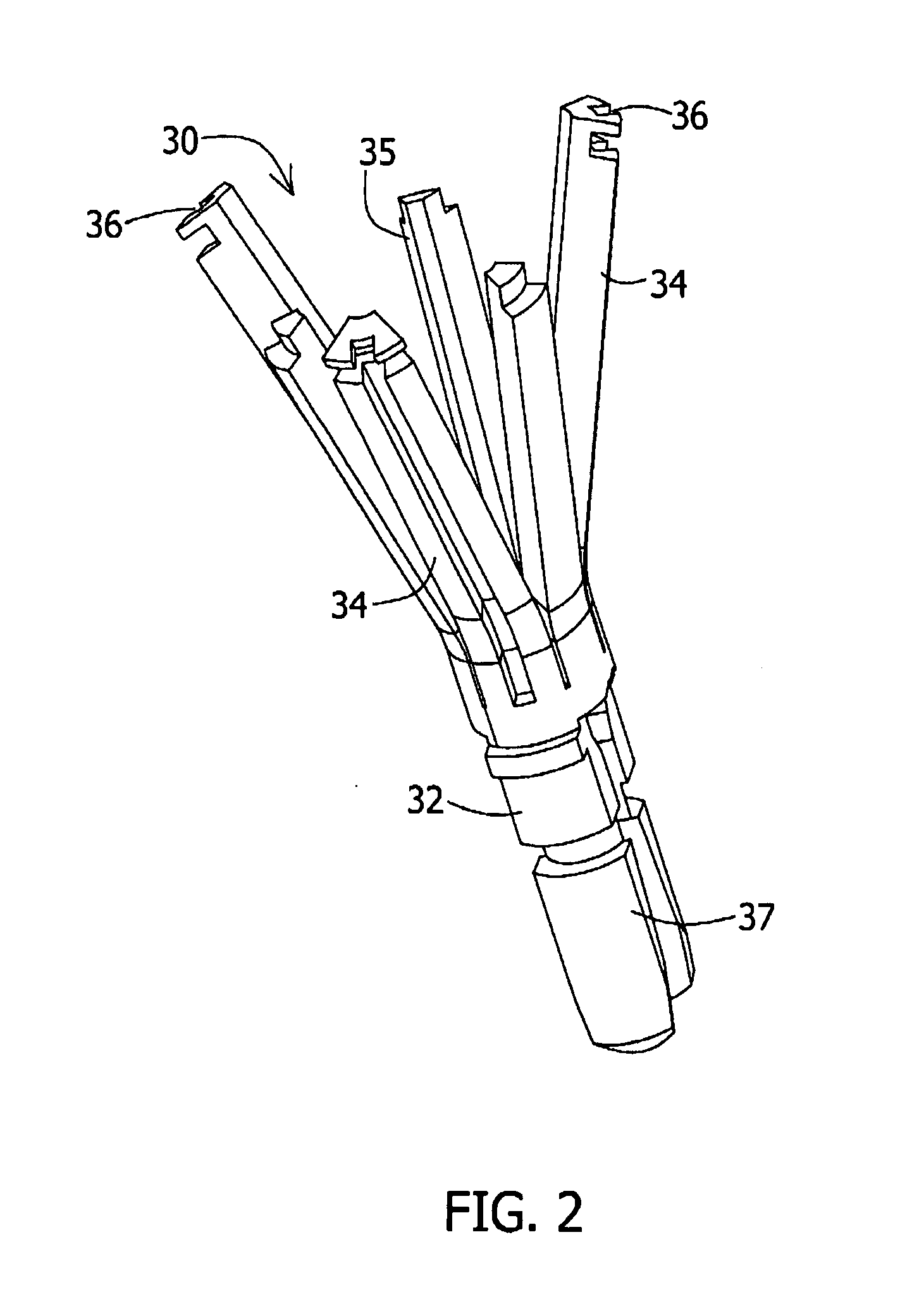
[0062]FIGS. 2 and 3 provide enlarged views of a three-prong loading tool (30) in an open state and in a closed state, respectively. The loading tool (30) has a base (32) and three prongs (34), extending the...


PUM


Abstract

A loading tool for withdrawing, crimping, and loading a stent-mounted valve into a delivery catheter, and for pushing the stent-mounted valve from the delivery catheter into a native heart valve orifice. The loading tool comprises at least one connector adapted for being removably connected to the stent of the stent-mounted valve. A crimping tool having a generally converging shape is adapted for use with the loading tool. Following connection of the loading tool to the stent-mounted valve, the loading tool operates to allow the stent-mounted valve to be drawn through the crimping tool, and loaded, in a crimped state, into a delivery catheter. Also disclosed is a kit of the of the various components for effecting the delivery of the stent-mounted valve and a method for withdrawing, crimping, and loading a stent-mounted valve from a storage container into a delivery catheter for the performance of a transcatheter valve implantation procedure.

Description

FIELD OF THE INVENTION[0001]The present invention of a device and methods generally relates to the field of cardiac medical technology. In particular, the device relates to a loading tool that may be used in crimping, loading, and delivery a stent-mounted valve or other expandable prosthetic device.BACKGROUND OF THE INVENTION[0002]Stents are bioprosthetic devices that are typically used for counteracting restenosis, or the repeated narrowing of a blood vessel. Stents may also be used, for example, as shown in U.S. Patent Application 2006 / 0149360 to Schwammenthal, et al, as a component of a stent-mounted heart valve with mounted leaflets. The stent mounted valve implant described there includes clamping fingers that secure its position at a native valve orifice of the heart.[0003]Such an implant is delivered to its site in the heart using a catheter assembly. To pass through the catheter, the prosthetic valve must be collapsed to a smaller profile. However, since the stent-mounted pr...

Claims


Application Information

Patent Timeline
Patent Type & Authority Applications(United States)
IPC IPC(8): A61F2/24
CPCA61F2/0095A61F2/2418A61F2/2436A61F2230/0054A61F2/2427A61F2220/0016A61F2002/9522A61F2/9522A61F2/2415
Inventor TUVAL, YOSISUDIN, YURIKILEMNIK, IDOKOVALSKY, IGORBENARY, RAFHAELEZEKIEL, GUY
Owner MEDTRONIC VENTOR TECH
Why Eureka
Try Eureka